Optimizing the energy consumption of your solar-powered IoT device can be a daunting task. We’re here to help. This blog post will walk you through testing your circuit to ensure that you are getting the most possible power from the solar panel into your battery. There are three tests:
- Measuring power into your circuit at different light levels – your circuit may perform more or less efficiently in shady and sunny conditions
- Measuring power into your circuit over a charge cycle – this will determine how long it takes to charge your battery from start to finish
- Calculating circuit efficiency – you need to calculate how much of the power into your circuit gets to the cells
Preparing for the Experiment
Required Tools and Equipment
If you are just getting started and have no idea where to begin, you can schedule an IoT consultation. If you’re not sure how big of a solar panel you will need, read how to Estimate Solar Irradiance for an IoT Device.
To begin, you will need the following:
- Download the spreadsheet. Log in to your Google account and click here to make your own copy of the document. You’ll be presented with a couple of tables: the first is intended to document some basic information about your experiment; the second is where you will record your experimental data.
- Solar panel: check out our in-stock standard panels or talk to us about a custom solar panel
- Your device
- A handheld or inline USB multimeter: we like the Makerhawk
- Solar power meter: we recommend the TES-1333
- (Optional) Thermometer: useful when fine-tuning a system in extreme temperatures
Information About the Experiment
While it is not strictly necessary to complete this table, it will help us aid you with any troubleshooting and it will also help you to remember these details down the road.
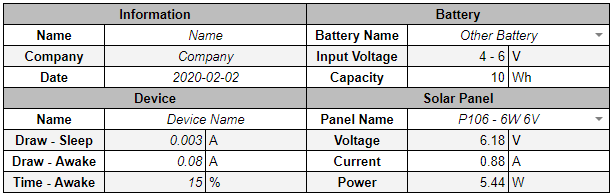
Go ahead and fill in all of the fields marked in italics and select your battery and solar panel from the drop-down cells. If you are using a non-Voltaic battery, feel free to head over to the last sheet on the document and edit the dictionary definition for Other Battery.
Measuring Solar Intensity and Solar Power Into an IoT Device
The goal of this first test is to see how much power is delivered by the panel into your circuit at different light intensities (AKA brightness, flux, irradiance), from shady conditions to bright sunlight. With this data, we can spot problems in your circuit and make recommendations on how to improve. These changes can improve the performance of your device, especially during the lowest light periods of the year.
Before we start, ensure that your battery is around 50% full. You can record the battery voltage along the way, but each of the measurements will be relatively quick–so the battery should stay at this level throughout.

Example setup of a 3.5W panel using the Particle Boron circuit to charge a LiPo battery.
Begin by orienting the solar panel directly toward the sun. Mount your solar power meter along the same axis so that you are measuring the intensity of the light falling onto the panel. Note that even a small discrepancy in the angles can throw off your experimental results, so you’ll want to make sure that the panel and the solar meter are closely aligned. Connect your multimeter to the panel, but leave your circuit disconnected.
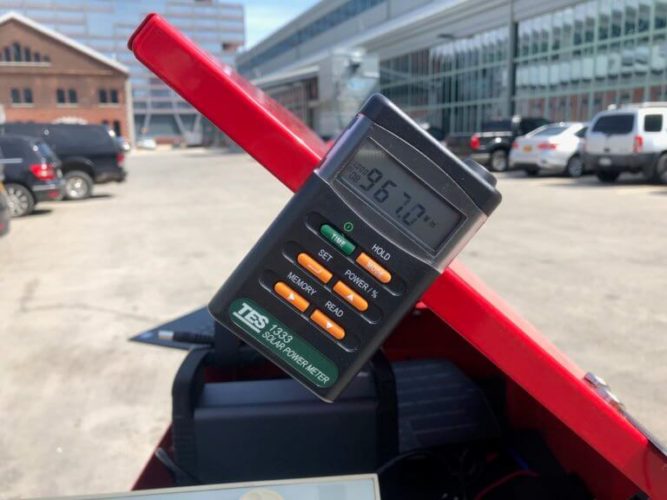
Solar intensity reading. Note the panel and the light meter are pointed the same direction.
Delete the example data marked in italics and record your first line by noting the solar intensity and open-circuit voltage. Next, connect your device to the panel with the multimeter inline. Ensure that the solar intensity has not changed–it can fluctuate quite rapidly–and record the voltage and current. The panel power will be calculated in the next column. The final column scales the power to a nominal solar intensity of 1000 watts per square meter.
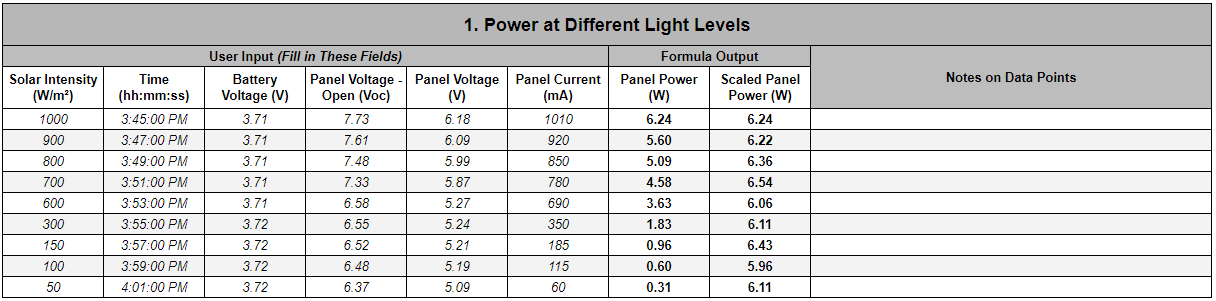
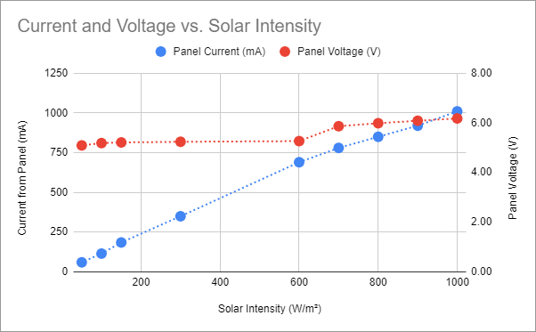
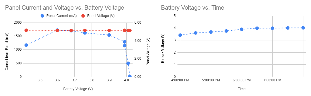
Repeat the process at a variety of light levels. You can alter the amount of incident light by angling the panel away from the sun, moving into the shade, or waiting for clouds to pass overhead. Once you have gathered data at a variety of light levels you can plot the results and get a graph that looks something like this:
Measuring Battery Voltage Across a Charge Cycle
The second sheet of the document contains a similar table that will help you understand how long it takes the circuit to charge from solar. This test will work best on a clear, sunny day. Find a spot with clear access to the sun.
Beginning with an empty battery, follow the same procedure as above, taking measurements at time intervals rather than at different light intensities. The experiment can be run at a fixed solar intensity, or left in the open for a more realistic exposure cycle. Measurements should be concentrated towards the second half of the cycle when the input starts to taper off. The two output graphs should look something like the following:
Calculating Circuit Efficiency
The third sheet contains the final experiment, and can be more complicated. It is designed to test the relationship of the power flowing from the panel to the power flowing into your device’s battery. It can be done with a solar panel or with a DC power supply. The ratio of the two is the efficiency of that circuit which can be tweaked by adjusting the MPP voltage. For more information, see the article How to Select MPP Voltage on a Solar Charge Controller.
For this experiment you will need to measure the power flowing at both points in the circuit. It is best to have two separate multimeters, but everything can be accomplished taking measurements one at a time. You can get creative here and perform any number of specific experiments with parameters (e.g. limiting current, battery state-of-charge) at various levels.
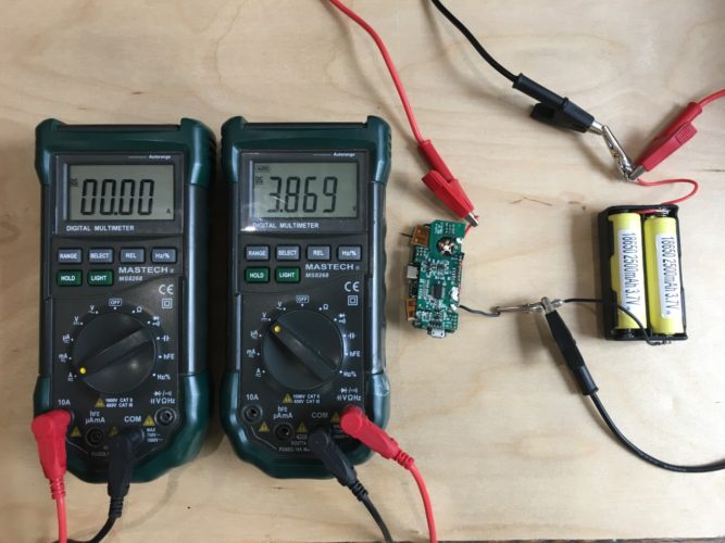
Setup to measure voltage and current from a charge circuit into LiIon 18650 cells.
Tweaking the MPP voltage and optimizing your circuit’s power consumption requires focused engineering efforts that will pay off by ensuring that your device will operate for extended periods of time in inclement weather. This spreadsheet should help you get started on the process. Reach out to us for engineering support or advice and we will help you get your project up and running!
Great info thanks. I’m planning to use a 6V 9w panel a available through Adafruit to charge my electronics while I ride RAGBRAI