Project Overview
Solar powered asset trackers present a number of interesting design challenges. You have a device with variable power consumption moving across geographic regions with an inconsistent orientation. In addition, the device is subject to a number of challenging environmental variables like vibration, pressure washers and greater than normal thermal cycling.
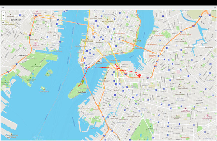
To highlight some of our thinking on some of these issues, we built a solar powered GPS tracker using the Actinius Icarus IoT Board v2 based on Nordic’s nRF9160 chip. The tracker uses a custom solar panel in a polycarbonate lens and sends tracking data to a Losant dashboard.
In this post, we’ll cover:
- Estimating power production of a solar-powered asset tracker
- An introduction to Actinius’ Icarus IoT Board
- Measuring system power consumption
- Publishing the data on a dashboard
Parts
- Actinius Icarus IoT Board v2
- RF Antenna
- GNSS Active Patch Antenna
- 3.7V 1600mAh Battery 704050 Lithium Polymer Ion Rechargeable Li-ion Li-Po Battery
- Custom polycarbonate solar panel (our P124 with G108 is a good off the shelf alternative)
- Custom 3D printed enclosure
- Double sided VHB tape
Background
Actinius is a Dutch research and development company that specializes in hardware and software for IoT. They recently released Icarus, a development board with GPS capabilities. The board has built in solar charging capability and low power management and seemed like an easy way for us to get started with a demonstration product.
Power Production Profiles in Asset Tracking
Asset trackers may be mounted on a roof or side of a tractor trailer or other asset. Both have advantages and disadvantages and may be constrained by the application.
If roof mounted, the panel will have consistent access to the sun, but the horizontal surface will receive relatively little light in December when the sun is mostly low in the sky.
A panel mounted vertically could be facing any cardinal direction. It will often perform better than the roof mounted panel when facing mostly south, but worse when facing north. To estimate the power of such a panel, we take the average of each direction.
Consider a 1 Watt panel in Minneapolis, MN in December and June.
| Mounting | Average Available Power Per Day December (Watt hours) | Average Available Power Per Day June (Watt hours) |
| Roof | 0.8 | 4.3 |
| Side – South | 1.75 | 1.89 |
| Side – East | 0.62 | 2.38 |
| Side – North | 0.16 | 1.15 |
| Side – West | 0.62 | 2.38 |
| Side – Average | 0.79 | 1.95 |
If we expected the asset to spend equal time in every direction, the power production would be consistent with each method in December. In reality, a trailer is not going to point in each direction equally so you will have some trailers with better performance and some with worse. In June, the roof mounting method would, on average, produce double the power.
Solar Panel and System Assembly
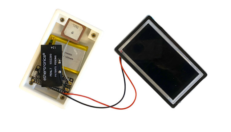
For this project, we used one of our custom panels. This panel is 0.9 Watt, 6 Volts and uses Sunpower cells potted into a custom Lexan polycarbonate lens. This panel has good impact and UV resistance and forms the “lid” of our design.
![]()
For the case, we 3D printed an enclosure to match the panel. This is how it stacks up.
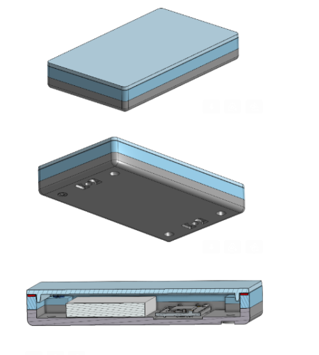
One of the most common ways to waterproof the panel to the enclosure is with VHB, and we use it to form a custom-sized gasket that sits on the perimeter of the enclosure.
The Actinius Icarus IoT Board
The Icarus comes with an nRF9160 modem from Nordic Semiconductor, an accelerometer, SPI Flash, GPS, a LiPo charger, and Cellular data (LTE-M / NB-IoT). The board can be powered by a LiPo/Li-Ion battery, USB, or solar panel and battery combination.
The board is designed in the standard Adafruit Feather form factor, featuring a 12 and 16-pin header with 0.1-inch spacing and built-in USB charging to allow users to power their board with a LiPo battery and recharge it via USB.
The VIN for solar pin allows the board to be powered from a solar panel, making it suitable for remote or mobile applications where traditional power sources may not be available.
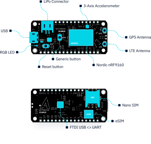
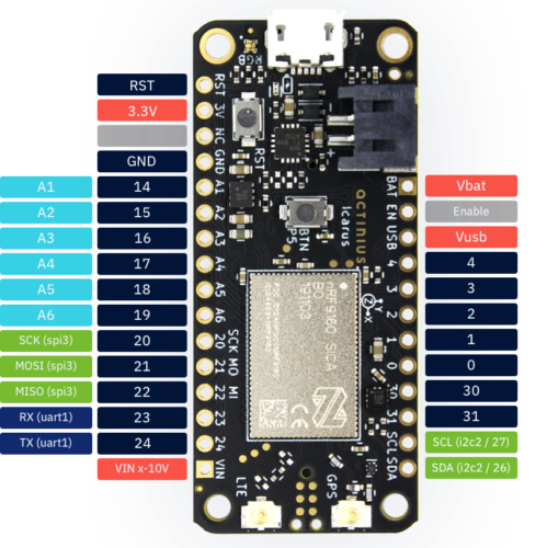
The GPS receiver on the Icarus is embedded into the modem of the nRF9160. To successfully get a GPS fix and receive location data, an active external GPS antenna must be connected (with a u.fl connector). An example of an antenna that can be used is the Molex GNSS active patch antenna.
Getting started
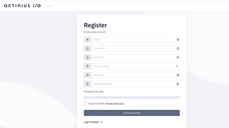
To get started with the Icarus IoT board, register for an account at actinius.io.
Once you have created an account and verified your email address, you can register your device, read product documentation, view other products and accessories, and get access to the Actinius Serial Programmer (on Actinius I/O). The Serial Programmer allows you to upload programs to your device from a browser (Chrome, Chromium, Edge, or Opera).
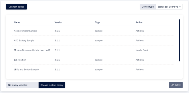
To use the Serial Programmer you’ll need to first register your device which you can do in the portal. Here are the following steps for using the programmer :
- Connect your device to your computer through USB.
- Navigate to the Serial Programmer.
- Select Connect device and choose the correct port.
- Select your device from the drop-down menu on the right.
- Select a pre-built application from the list or add your own app_update.bin. We used the GPS sample found in the documentation.
- Click the Write button to flash.
- Follow the instructions on the screen to put your board into MCUBoot mode.
The board will be flashed with the firmware application. Once flashing is finished, press the reset button on your board to start the application.
The data collected will be automatically uploaded to the Actinius console. You can then use a webhook to route the data elsewhere.
In our case we are sending the data to a Losant dashboard.

More Getting Started information can be found here.
Power Consumption
Once the board was programmed, we began collecting power consumption data under various conditions. Using the Qoitech Otii Ace Pro we collected the following:
On startup:
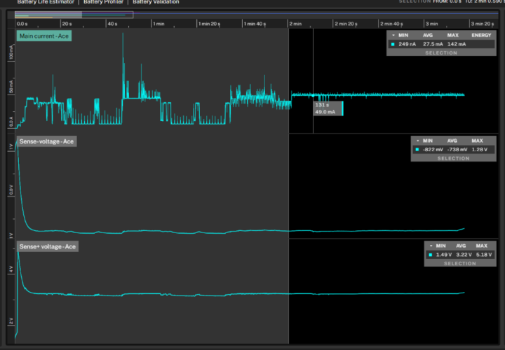
When connecting:
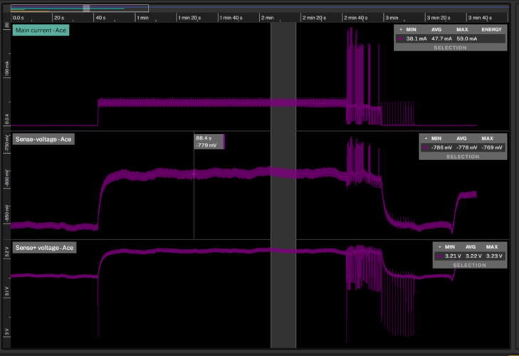
When transmitting:
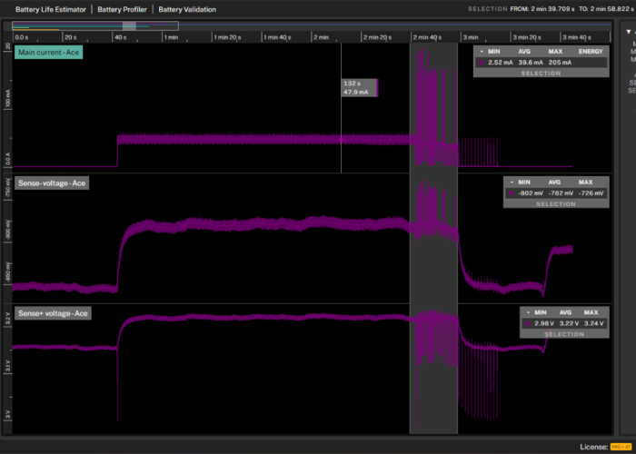
| Power Consumption in Different States (mW) | |
| Boot Up (Avg of 1st 2 minutes) | 108.845 |
| Connecting | 190.7 |
| Transmission | 158.5 |
| Idle | 0.00014 |
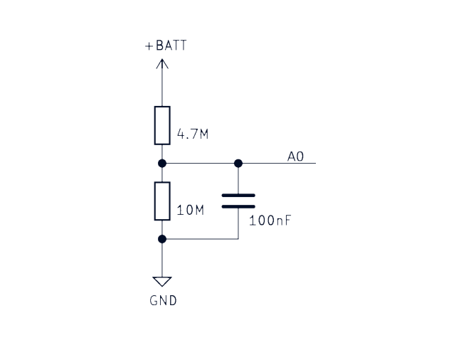
Battery voltage measurement
As in all IoT projects, it is essential to monitor current battery voltage levels. The Icarus board allows you to monitor your battery voltage through an internal voltage divider circuit. The ADC (Analog to Digital Converter) battery voltage sample shows you how to set up the ADC to read the battery value from pin A0.
Actinius I/O Serial Programmer
We’d like to thank Actinius for the opportunity to try out the Icarus IoT board with our polycarbonate solar panel. If you are interested in solar panels for solar powered asset tracking, please get in touch with us.
- Follow battery cell instructions for safe charging and storage
- Always use cables and adapters that are made specifically for the device
- Store and charge batteries away from anything flammable
- Ensure your charge controller includes over and under temperature protection and that these settings match the specifications on your battery cells
- Ensure your charge controller has over charge, over discharge and short circuit protection
If a battery changes shape or is leaking, you should discontinue use immediately.
Leave a Reply