
Overview:
Learn how to create a LoRa wireless networked device with an Adafruit Feather M0 RFM95 LoRa Radio 900MHz connected to a sensor and powered by a e-Peas energy harvester and a Lithium Ion Capacitor (LIC). In this tutorial, you will:
- Program your board using the Arduino IDE
- Measure and monitor the battery voltage
- Enable sleep to make the device more efficient
- Deploy system with appropriately sized solar panel and battery
- Publish data to a Qubitro dashboard
An IoT Feather M0 with Barometric Sensor
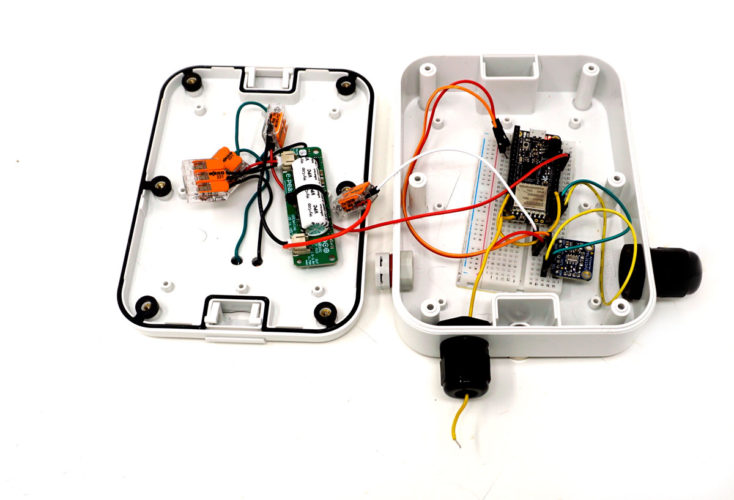
This tutorial will cover powering an Adafruit Feather M0 radio with two 0.3 Watt, 2 Volt solar panels, and an e-Peas energy harvester. It will also cover connecting the Feather to The Things Network (TTN). This simple project will introduce you to the Feather M0 module, working with a barometric sensor, coding, and LoRaWAN, all of which you can apply to other long range, low power, secure, standardized, low cost, and flexible LoRaWAN applications.
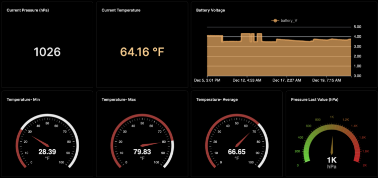
Qubitro Dashboard. Click here for live data
Parts Needed
- The Things Network Gateway if the network is not available in your area. I’m using The Things Indoor LoRaWAN WiFi Gateway – 8 Channel LoRa 900 MHz
- Adafruit Feather M0 with RFM95 LoRa Radio – 900MHz – RadioFruit
- Stacking Headers for Feather – 12-pin and 16-pin female headers
- MPL3115A2 – I2C Barometric Pressure/Altitude/Temperature Sensor
- Stacking Headers
- Breadboard
- Wires
- Wire clippers
- Wire Strippers
- JST 2.0 PH 2-Pin Connector Plug with Wires Cables
- Lithium Ion Capacitor Solar Charger e-Peas Energy Harvester (C117)
- 1-2 0.3 Watt 2 Volt Mini Solar Panel – ETFE
- Mini Solar Ready Enclosure
- ETFE Panel Magnet Mount Set

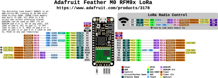
The Adafruit Feather M0 with an RFM9x LoRa 868/915 MHz radio module that transmits and receives small packets of data is designed to make flexible wireless networks without the high power requirements of WiFi.
Each Adafruit LoRa device comes with a small label that contains a MAC address in the form 98:76:B6:xx:yy:zz. This might be a sticker attached to the device itself or included separately. The MAC address is needed when connecting the Feather to LoRaWAN. Speaking from experience, I suggest taking a photo of this sticker as a backup plan for when the sticker goes missing.
To make it easy to use the Feather for portable projects, Adafruit added a connector for a 3.7V Lithium polymer battery. The Feather can run off a battery or a micro USB, and you can use the USB input to recharge the battery. The Feather will automatically switch from the battery to USB power when available. The battery is also tied through a divider to an analog pin, so you can measure and monitor the battery voltage to detect when you need a recharge.
The module can be programmed in the Arduino IDE. To get the battery’s voltage, connect the battery to D9 (A7), read the pin’s voltage, and then double it to get the battery voltage. Here is the code you’ll need:
[code lang=”arduino”]#define VBATPIN A7
double measuredvbat = analogRead(VBATPIN);
measuredvbat *= 2; // we divided by 2, so multiply back
measuredvbat *= 3.3; // Multiply by 3.3V, our reference voltage
measuredvbat /= 1024; // convert to voltage
Serial.print("VBat: " ); Serial.println(measuredvbat);[/code]
While one can set up two Feather M0 with RFM9x LoRa 868/915 MHz radio modules to transmit and receive data from one another, we will use the module to communicate with a Things Gateway.
It’s important to note that LoRaWAN (Long Range Wide Area Network) projects are unsuitable for applications where you must send a lot of data. LoRaWAN is a wireless communication protocol that connects devices over long distances with minimal power consumption.
It is also essential to understand that LoRa and LoRaWAN are not interchangeable terms. LoRa refers to the type of hardware that is responsible for wireless modulation communication that operates with very low power consumption, while LoRaWAN refers to a network protocol. LoRa is the physical layer, and LoRaWAN is the MAC (media access protocol) layer.
Parts of the System
- The feather is an end node, a part of the system equipped with one or more sensors that collects and transmits data.
- The The Things Indoor LoRaWAN WiFi Gateway is our Gateway.
- The Things Network (TTN) is the Network Server, and
- Qubitro, a platform that provides tools and services for connecting, managing, and analyzing IoT devices and data, is the application server.
LoRa operates in various frequency bands. Which band you work in depends on your region. In North America, the range is between 902 MHz and 928 MHz. In Europe, there are two bands; one range is between 863-870 MHz, and the other is at 433MHz. Asia has two bands: one between 865 to 867 MHz and the other between 920 to 923 MHz. If you’re curious, here’s a list of frequencies by country.
Step 1: Gather Your Parts
Step 2: Solder Your Headers and Antenna
Your radio module needs an antenna. For a DIY antenna, cut a stranded or solid core wire to the proper length for your module/frequency:
- 433 MHz – 6.5 inches, or 16.5 cm
- 868 MHz – 3.25 inches or 8.2 cm
- 915 MHz – 3 inches or 7.8 cm
Strip a mm or two off the end of the wire, tin and solder into the ANT pad on the very right hand edge of the Feather.

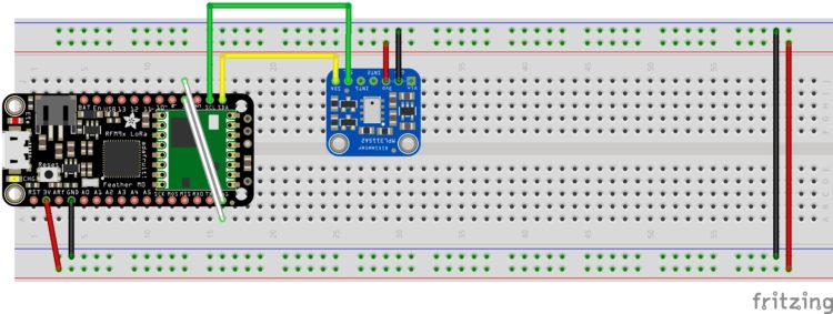
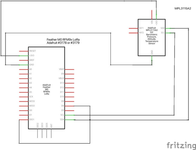
Step 3: Wire the Circuit
- By default Adafruit Feather M0’s pin GPIO6 and DIO1 are not connected. Please ensure they are connected.

- Wire up the basic circuit for now. After everything is working, we’ll add solar.
Step 4: Set Up the Gateway
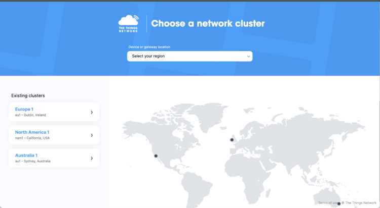
- Navigate to the TTN website to log in or to create an account.
- Navigate to Console. Choose your cluster:
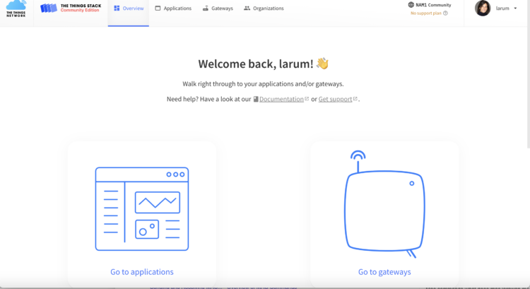
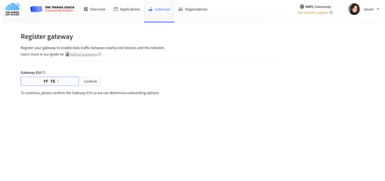
- Select Register Gateway or Go to Gateway:
- Add your Gateway EUI. The Gateway EUI is obtained by writing down the first six digits of the 12-digit alphanumeric number found on the top left corner of the sticker below the QR code on the bag where the gateway was packaged. This 12-digit number is the gateway ID. After the first six digits, insert FFFE, and then finish by writing down the last six digits.
Example: 2FA02C60AA3C —> 2FA02CFFFE60AA3C
The gateway EUI is 2FA02CFFFE60AA3C
- Use your WiFiPW on the back of the device as your claim authentication code. The gateway Wifi password is located after the phrase “WiFi PW:” on the sticker on the back of the device. This alphanumeric Wifi password will look similar to “LwtHsNYK”:
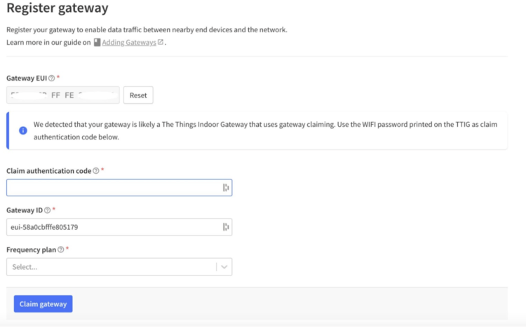
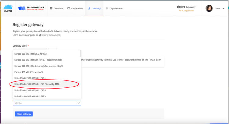
- Select your region. In the US, we’ll select FSB 2:
- Click on Claim Gateway.
- Configure the Gateway:
- Plug in the gateway.
- Press the reset button for 5 seconds (on the bottom of the gateway next to the USB port) or until the light blinks GREEN-RED rapidly a couple of times.
- After resetting, press the SETUP button for 10 seconds (at the top of the gateway) until the light blinks RED rapidly. The gateway’s Wifi network MiniHub-XXXXXX will now be visible (at least for the next 10 minutes).
- On your computer, select the MiniHub network.
- Open a browser window and type 192.168.4.1 in the address bar type. Then press Enter to access the Wifi config page.
- Select your home/office Wifi network from the Scanned Networks list and enter your Wifi network password.
- Select the “Save and Reboot” option at the bottom of the screen.
If everything is working correctly and the gateway can connect to The Things Network (TTN) via your home/office Wifi, the light on top of the gateway will be solid green after about a minute.
- Plug in the gateway.
Step 5: Register your Feather
You need to register your Feather with The Things Network to get the three unique identifiers you’ll need for your code: APPEUI, DEVEUI, and APPKEY.
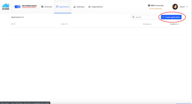
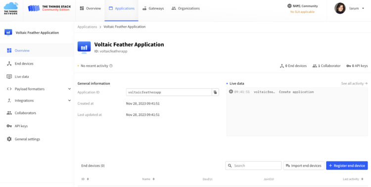
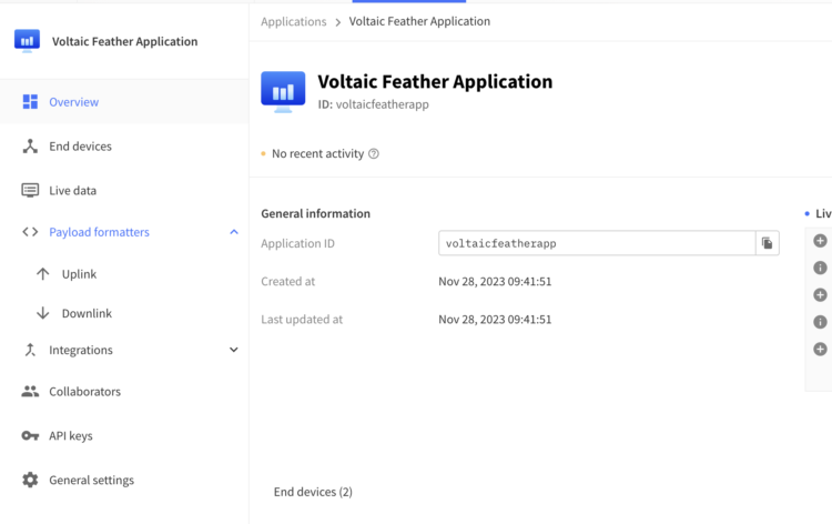
- Navigate to Applications, or if you are logging in again, click on Go to Applications:
- Click on the + Create Application:
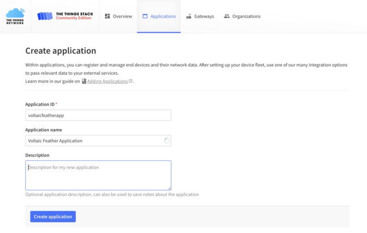
- Provide an Application ID and an Application name for your application and then click on Create application:
- Click on +Register end device:
- Select Enter end device specifics manually:
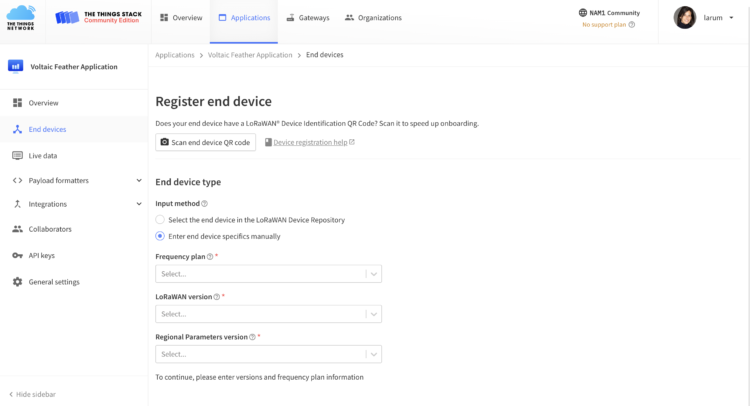
- Select your region and a LoRaWAN version. The LoRaWAN protocol is developed and maintained by the LoRa Alliance
Version Release date 1.0 January 2015 1.0.1 February 2016 1.0.2 July 2016 1.1 October 2017 1.0.3 July 2018 1.0.4 October 2020 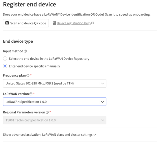
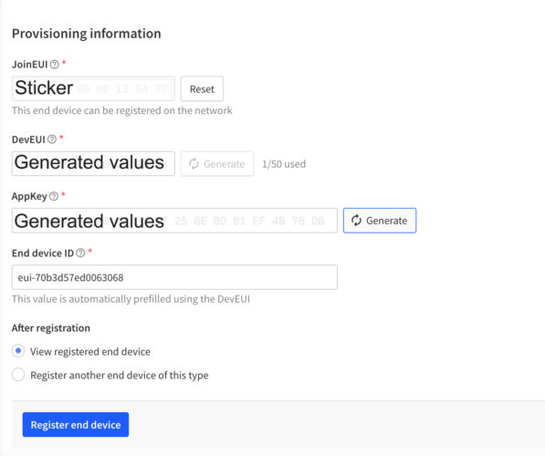
- For the provisioning, locate the sticker that came with your Feather. Enter the first six hex values, then add 00 00 followed by the last six hex digits: XX XX XX 00 00 XX XX XX

- Click Generate for the DevEUI:
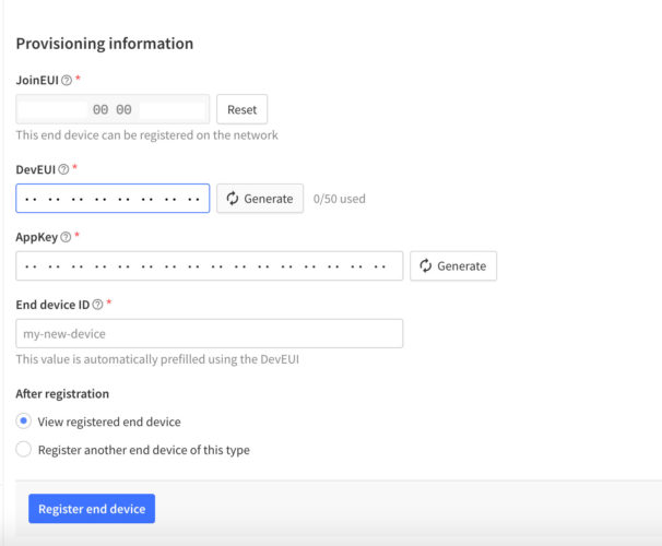
- Click Generate for the AppKey:
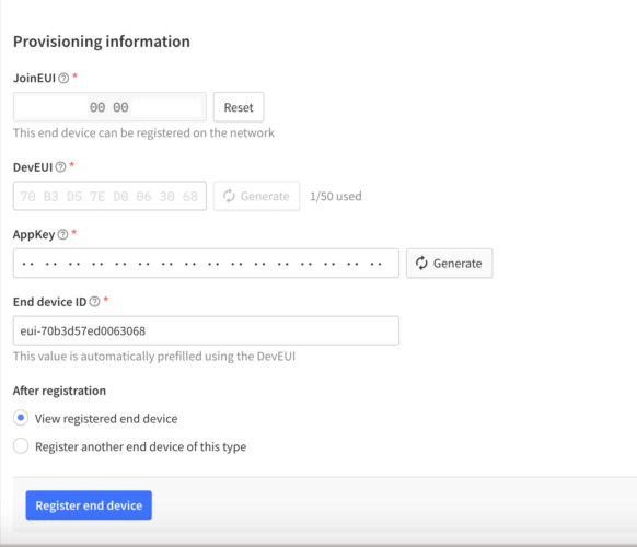
- Click Register end device:
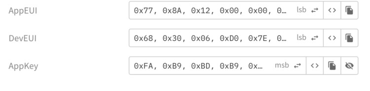
- You will need the information found under Activation Information. Click on the <> to change the format to little-endian. For the AppEUI you need to get the lsb (least significant byte first) version. To toggle between msb ( most significant byte first) and lsb, click on the two way arrows:
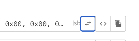
- Click on the Copy icon and paste the AppEUI in a document that you can refer to later.
- Do the same (lsb) for the DevEUI and paste the lsb version into your document:
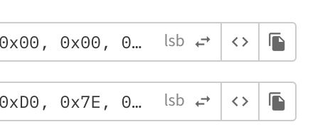
- The AppKey will need to be the msb format so just copy it into your document:
- Save your separate document somewhere where you can find it later:
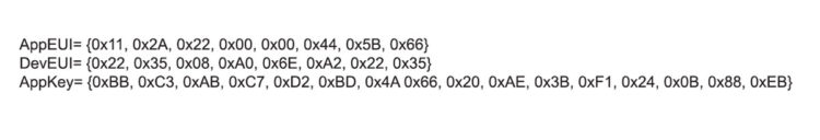
Example text file
Step 6: Arduino
Open the Arduino IDE
- Open or install the Arduino IDE. If you do not have the latest version of the Arduino IDE installed:
- Navigate to the Arduino website.
- Select your operating system and download the software.
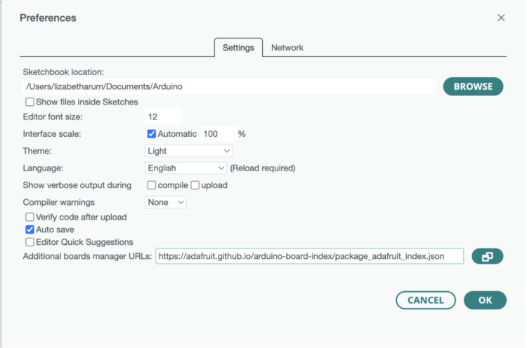
- To program the Feather M0 board using Arduino IDE, you need to install the package_adafruit_index.json file. Open the Preferences window in the Arduino IDE.
- Go to File > Preferences.
- Enter the following into the “Additional Board Manager URLs” field: “https://adafruit.github.io/arduino-board-index/package_adafruit_index.json”
- Here’s a short description of each of the Adafruit supplied packages that will be available in the Board Manager when you add the URL:
- Adafruit AVR Boards – Includes support for Flora, Gemma, Feather 32u4, Trinket, & Trinket Pro.
- Adafruit SAMD Boards – Includes support for Feather M0 and M4, Metro M0 and M4, ItsyBitsy M0 and M4,
- Circuit Playground Express, Gemma M0 and Trinket M0
- Arduino Leonardo & Micro MIDI-USB – This adds MIDI over USB support for the Flora, Feather 32u4, Micro and Leonardo using the arcore project (https://adafru.it/eSI).
- Adafruit AVR Boards – Includes support for Flora, Gemma, Feather 32u4, Trinket, & Trinket Pro.
- Click OK.
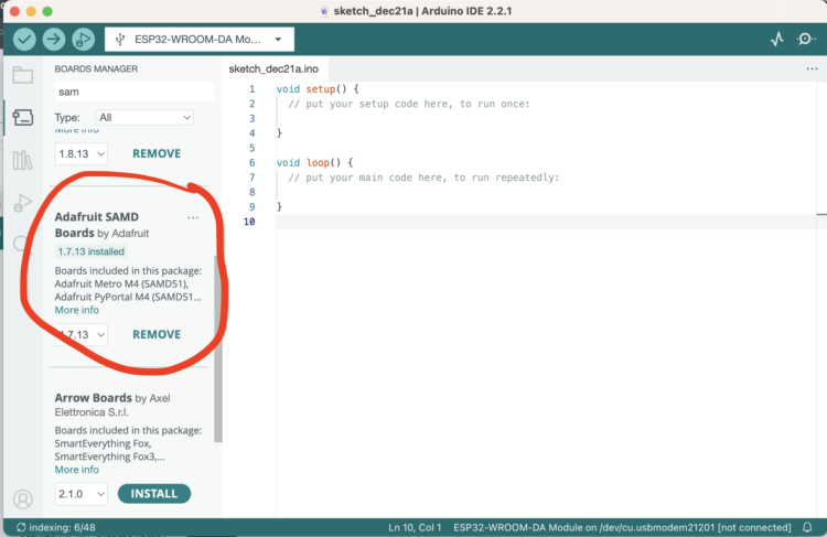
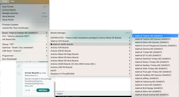
- Open the Boards Manager. Go to Tools > Board >Boards Manager…
- Search for Adafruit SAMD Boards by Adafruit and Arduino SAMD Boards
Step 7: Setting up Your Feather M0
Connect your Feather M0 into your computer through USB. Then, follow these steps:
- Open the Arduino IDE.
- Select your Board in the Tools Board menu (in our case, it’s the Adafruit Feather M0 -SAMD21)
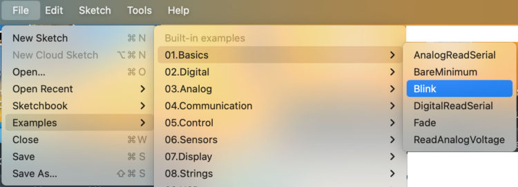
- Select the Port (if you don’t see the COM Port in your Arduino IDE and you are running Windows 7 or 8, you may need to install the To test that it all works, open the Blink Example:
- Click on the Upload button:
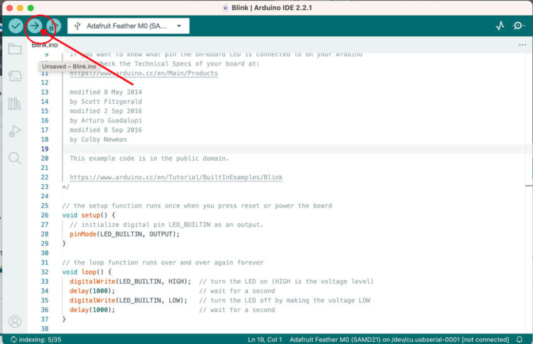
If everything went as expected, you should see a “Done uploading.” message. If you don’t, you’ll need to troubleshoot. If your upload was successful, you’ll get a bunch of red text that tells you that the device was found and it was programmed, verified & reset.
After uploading, you may see a message saying “Disk Not Ejected Properly” about the …BOOT drive. You can ignore that message: it’s an artifact of how the bootloader and uploading work.
Step 8: Set Up Your Program
Create a new Sketch and save it as feather_temperature
Step 9: Importing Libraries
You’ll need a few libraries, so go to tools and select Manage Libraries…
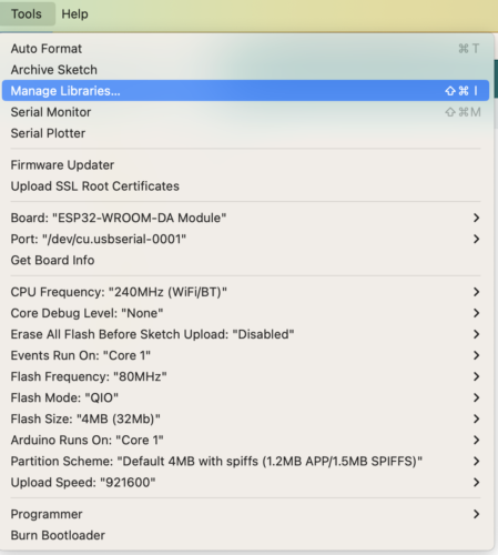
You’ll need to Install:
- MCCI Arduino LoRaWAN library
- MCCI LoRaWAN LMIC library
- Adafruit MPL3115A2 library
- Adafruit Sensor Lab library
When prompted, install the library and any dependencies.
Step 10: Copy and paste the code
Copy and paste the code into your sketch:
[code lang=”arduino”]
/*******************************************************************************
* derived from The Things Network – Sensor Data Example
* Example of sending a valid LoRaWAN packet to The Things Networ using a Feather M0 LoRa.
* Learn Guide: https://learn.adafruit.com/the-things-network-for-feather
* Copyright (c) 2015 Thomas Telkamp and Matthijs Kooijman
* Copyright (c) 2018 Terry Moore, MCCI
* Copyright (c) 2018 Brent Rubell, Adafruit Industries
*
* Permission is hereby granted, free of charge, to anyone
* obtaining a copy of this document and accompanying files,
* to do whatever they want with them without any restriction,
* including, but not limited to, copying, modification and redistribution.
* NO WARRANTY OF ANY KIND IS PROVIDED.*******************************************************************************/
#include <lmic.h>
#include <hal/hal.h>
#include <Adafruit_MPL3115A2.h>
Adafruit_MPL3115A2 baro;
#define VBATPIN A7// This EUI must be in little-endian format, so least-significant-byte
// first. When copying an EUI from ttnctl output, this means to reverse
// the bytes. For TTN issued EUIs the last bytes should be 0xD5, 0xB3,
// 0x70.
static const u1_t PROGMEM APPEUI[8] = {[XXX]};
void os_getArtEui(u1_t* buf) {
memcpy_P(buf, APPEUI, 8);
}// This should also be in little endian format, see above.
static const u1_t PROGMEM DEVEUI[8] = {[XXX]};
void os_getDevEui(u1_t* buf) {
memcpy_P(buf, DEVEUI, 8);
}// This key should be in big endian format (or, since it is not really a
// number but a block of memory, endianness does not really apply). In
// practice, a key taken from the TTN console can be copied as-is.
static const u1_t PROGMEM APPKEY[16] = { [XXX] };
void os_getDevKey(u1_t* buf) {
memcpy_P(buf, APPKEY, 16);
}// payload to send to TTN gateway
static uint8_t payload[7];static osjob_t sendjob;
// Schedule TX every this many seconds (might become longer due to duty
// cycle limitations).
const unsigned TX_INTERVAL = 30;// Pin mapping for Adafruit Feather M0 LoRa
// /!\ By default Adafruit Feather M0's pin 6 and DIO1 are not connected.
// Please ensure they are connected.const lmic_pinmap lmic_pins = {
.nss = 8,
.rxtx = LMIC_UNUSED_PIN,
.rst = 4,
.dio = { 3, 6, LMIC_UNUSED_PIN },
.rxtx_rx_active = 0,
.rssi_cal = 8, // LBT cal for the Adafruit Feather M0 LoRa, in dB
.spi_freq = 8000000,
};void printHex2(unsigned v) {
v &= 0xff;
if (v < 16)
Serial.print('0');
Serial.print(v, HEX);
}void onEvent(ev_t ev) {
Serial.print(os_getTime());
Serial.print(": ");
switch (ev) {
case EV_SCAN_TIMEOUT:
Serial.println(F("EV_SCAN_TIMEOUT"));
break;
case EV_BEACON_FOUND:
Serial.println(F("EV_BEACON_FOUND"));
break;
case EV_BEACON_MISSED:
Serial.println(F("EV_BEACON_MISSED"));
break;case EV_BEACON_TRACKED:
Serial.println(F("EV_BEACON_TRACKED"));
break;
case EV_JOINING:
Serial.println(F("EV_JOINING"));
break;
case EV_JOINED:
Serial.println(F("EV_JOINED"));
{
u4_t netid = 0;
devaddr_t devaddr = 0;
u1_t nwkKey[16];
u1_t artKey[16];
LMIC_getSessionKeys(&netid, &devaddr, nwkKey, artKey);
Serial.print("netid: ");
Serial.println(netid, DEC);
Serial.print("devaddr: ");
Serial.println(devaddr, HEX);
Serial.print("AppSKey: ");
for (size_t i = 0; i < sizeof(artKey); ++i) {
if (i != 0)
Serial.print("-");
printHex2(artKey[i]);
}Serial.println("");
Serial.print("NwkSKey: ");
for (size_t i = 0; i < sizeof(nwkKey); ++i) {
if (i != 0)
Serial.print("-");
printHex2(nwkKey[i]);
}
}// Disable link check validation (automatically enabled
// during join, but because slow data rates change max TX
// size, we don't use it in this example.
//LMIC_setLinkCheckMode(0);
break;/*
|| This event is defined but not used in the code. No
|| point in wasting codespace on it.
||
|| case EV_RFU1:
|| Serial.println(F("EV_RFU1"));
|| break;
*/case EV_JOIN_FAILED:
Serial.println(F("EV_JOIN_FAILED"));
break;
case EV_REJOIN_FAILED:
Serial.println(F("EV_REJOIN_FAILED"));
break;
case EV_TXCOMPLETE:
Serial.println(F("EV_TXCOMPLETE (includes waiting for RX windows)"));
if (LMIC.txrxFlags & TXRX_ACK)
Serial.println(F("Received ack"));
if (LMIC.dataLen) {
Serial.println(F("Received "));
Serial.println(LMIC.dataLen);
Serial.println(F(" bytes of payload"));
}
// Schedule next transmission
os_setTimedCallback(&sendjob, os_getTime() + sec2osticks(TX_INTERVAL), do_send);
break;
case EV_LOST_TSYNC:
Serial.println(F("EV_LOST_TSYNC"));
break;
case EV_RESET:
Serial.println(F("EV_RESET"));
break;
case EV_RXCOMPLETE:
// data received in ping slot
Serial.println(F("EV_RXCOMPLETE"));
break;
case EV_LINK_DEAD:
Serial.println(F("EV_LINK_DEAD"));
break;
case EV_LINK_ALIVE:
Serial.println(F("EV_LINK_ALIVE"));
break;
/*
|| This event is defined but not used in the code. No
|| point in wasting codespace on it.
||
|| case EV_SCAN_FOUND:
|| Serial.println(F("EV_SCAN_FOUND"));
|| break;
*/case EV_TXSTART:
Serial.println(F("EV_TXSTART"));
break;
case EV_TXCANCELED:
Serial.println(F("EV_TXCANCELED"));
break;
case EV_RXSTART:
/* do not print anything — it wrecks timing */
break;
case EV_JOIN_TXCOMPLETE:
Serial.println(F("EV_JOIN_TXCOMPLETE: no JoinAccept"));
break;
default:
Serial.print(F("Unknown event: "));
Serial.println((unsigned)ev);
break;
}
}void do_send(osjob_t* j) {
// Check if there is not a current TX/RX job running
if (LMIC.opmode & OP_TXRXPEND) {
Serial.println(F("OP_TXRXPEND, not sending"));
} else {
// read the sensor
if (!baro.begin()) {
Serial.println("Could not find sensor. Check wiring.");
while (1);
}
// use to set sea level pressure for current location
// this is needed for accurate altitude measurement
// STD SLP = 1013.26 hPa
baro.setSeaPressure(1013.26);
float pressure = baro.getPressure();
//adjusted for fahrenheit
float temperature = (9 * baro.getTemperature()) / 5 + 32;
Serial.println("—————–");
Serial.print("pressure = ");
Serial.print(pressure);
Serial.println(" hPa");
Serial.print("temperature = ");
Serial.print(temperature);
Serial.println(" F");// float -> int
temperature = temperature / 100;
pressure = pressure / 1000;
// note: this uses the sflt16 datum (https://github.com/mcci-catena/arduino-lmic#sflt16)
uint16_t payloadTemp = LMIC_f2sflt16(temperature);
// int -> bytes
byte tempLow = lowByte(payloadTemp);
byte tempHigh = highByte(payloadTemp);
// place the bytes into the payload
payload[0] = tempLow;
payload[1] = tempHigh;
// float -> int
uint16_t payloadPressure = LMIC_f2sflt16(pressure / 10);
// int -> bytes
byte pressureLow = lowByte(payloadPressure);
byte pressureHigh = highByte(payloadPressure);
// place the bytes into the payload
payload[2] = pressureLow;
payload[3] = pressureHigh;
// Payload format Bytes: [(Bat-Voltage – 2) * 100]double measuredvbat = analogRead(VBATPIN);
measuredvbat *= 2; // we divided by 2, so multiply back
measuredvbat *= 3.3; // Multiply by 3.3V, our reference voltage
measuredvbat /= 1024; // convert to voltage
Serial.print("VBat: " ); Serial.println(measuredvbat);
measuredvbat = measuredvbat / 100;
uint16_t payloadBattery=LMIC_f2sflt16(measuredvbat);// int -> bytes
byte batteryLow = lowByte(payloadBattery);
byte batteryHigh = highByte(payloadBattery);
// place the bytes into the payload
payload[4] = batteryLow;
payload[5] = batteryHigh;// prepare upstream data transmission at the next possible time.
// transmit on port 1 (the first parameter); you can use any value from 1 to 223 (others are reserved).
// don't request an ack (the last parameter, if not zero, requests an ack from the network).
// Remember, acks consume a lot of network resources; don't ask for an ack unless you really need it
LMIC_setTxData2(1, payload, sizeof(payload) – 1, 0);
}// Next TX is scheduled after TX_COMPLETE event.
}void setup() {
delay(5000);
Serial.begin(9600);
Serial.println(F("Starting"));
// LMIC init
os_init();
// Reset the MAC state. Session and pending data transfers will be discarded.
LMIC_reset();
// Disable link-check mode and ADR, because ADR tends to complicate testing.
LMIC_setLinkCheckMode(0);
// Set the data rate to Spreading Factor 7. This is the fastest supported rate for 125 kHz channels, and it
// minimizes air time and battery power. Set the transmission power to 14 dBi (25 mW).
LMIC_setDrTxpow(DR_SF7, 14);
// in the US, with TTN, it saves join time if we start on subband 1 (channels 8-15). This will
// get overridden after the join by parameters from the network. If working with other
// networks or in other regions, this will need to be changed.
LMIC_selectSubBand(1);
// Start job (sending automatically starts OTAA too)
do_send(&sendjob);
}void loop() {
// we call the LMIC's runloop processor. This will cause things to happen based on events and time. One
// of the things that will happen is callbacks for transmission complete or received messages. We also
// use this loop to queue periodic data transmissions. You can put other things here in the `loop()` routine,
// but beware that LoRaWAN timing is pretty tight, so if you do more than a few milliseconds of work, you
// will want to call `os_runloop_once()` every so often, to keep the radio running.
os_runloop_once();}
[/code]Step 11: Adding your Activation Information
Update the [XXX]s with your saved AppEUI, DevEUI, and AppKey:
[code lang=”arduino”]static const u1_t PROGMEM APPEUI[8] = {<b>[XXX]</b>;// This should also be in little endian format, see above.
static const u1_t PROGMEM DEVEUI[8] = {<b>[XXX]</b>};// This key should be in big endian format (or, since it is not really a
// number but a block of memory, endianness does not really apply). In
// practice, a key taken from the TTN console can be copied as-is.
static const u1_t PROGMEM APPKEY[16] = { <b>[XXX]</b> };[/code]
Compile and upload the code.Step 12: Payload formatters
After uploading the code we’re going to send the data from the Feather to TTN and decode it.
Back in the TTN console, we need to add an uplink payload formatter.
- Click on Application, select your application and then select Payload formatters from the left menu:
- Click on Uplink.
- Select Custom Javascript formatter:
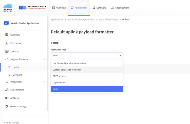
- Copy the following code and replace the existing javascript:
[code lang=”arduino”]// TTN Decoder for TTN OTAA Feather US915
function Decoder(bytes, port) {// Decode an uplink message from a buffer
// (array) of bytes to an object of fields.var decoded = {};
// temperature
rawTemp = bytes[0] + bytes[1] * 256;
decoded.degrees_F = parseFloat((sflt162f(rawTemp) * 100).toFixed(2));// pressure
rawPressure = bytes[2] + bytes[3] * 256;
decoded.pressure_hPa = parseFloat((sflt162f(rawPressure) * 10000).toFixed(2));// battery
rawBattery = bytes[4] + bytes[5] * 256;
decoded.battery_V = parseFloat((sflt162f(rawBattery) * 100).toFixed(2));
return decoded;
}function sflt162f(rawSflt16)
{
// rawSflt16 is the 2-byte number decoded from wherever;
// it's in range 0..0xFFFF
// bit 15 is the sign bit
// bits 14..11 are the exponent
// bits 10..0 are the the mantissa. Unlike IEEE format,
// the msb is explicit; this means that numbers
// might not be normalized, but makes coding for
// underflow easier.
// As with IEEE format, negative zero is possible, so
// we special-case that in hopes that JavaScript will
// also cooperate.
//
// The result is a number in the open interval (-1.0, 1.0);
//
// throw away high bits for repeatability.rawSflt16 &= 0xFFFF;
// special case minus zero:
if (rawSflt16 == 0x8000)return -0.0;
// extract the sign.
var sSign = ((rawSflt16 & 0x8000) != 0) ? -1 : 1;// extract the exponent
var exp1 = (rawSflt16 >> 11) & 0xF;// extract the "mantissa" (the fractional part)
var mant1 = (rawSflt16 & 0x7FF) / 2048.0;// convert back to a floating point number. We hope
// that Math.pow(2, k) is handled efficiently by
// the JS interpreter! If this is time critical code,
// you can replace by a suitable shift and divide.
var f_unscaled = sSign * mant1 * Math.pow(2, exp1 – 15);return f_unscaled;
}[/code]
Step 13: Characterize Power Consumption
The battery life of an end device is highly dependent on the spreading factor used. Higher spreading factors result in longer active times for the radio transceivers and shorter battery life. We’ll be using a spreading factor of 7, which provides the highest bit rate and longest battery life. You can see in the code where this is set:
[code lang=”arduino”]// Set the data rate to Spreading Factor 7. This is the fastest supported rate for 125 kHz channels, and it
//minimizes air time and battery power. Set the transmission power to 14 dBi (25 mW).
LMIC_setDrTxpow(DR_SF7, 14);[/code]
According to the specs, The power consumption of the radio is ~0.0003 A during full sleep, ~.12A during +20dBm transmit, and ~.04A during active radio listening.I tested my setup with a programmable power supply and collected the following data.
When the module was not sending data, I measured 0.015 amps. And when actively sending data, I measured .136 amps.
I found that for reading and sending data my device measured 0.0331 A. which makes sense if you look at the power consumption above.
0.04 A per active listening
0.136 A for transmitting
0.04 A *17/60 seconds = 0.0113 A
0.136 A * 3/60 seconds = 0.0068 A
0.018 A * 3.3V= 0.05 W
Or 0.05 W
If I ran the system continuously, meaning multiplying 0.05 Watts by 24 hours. I would be at 0.6 Watt hours per day and would need a much larger panel and battery.
Fortunately, I can put the board to sleep between readings and I only need about a about 20 seconds to read and send data.
[CP_CALCULATED_FIELDS id=”8″]
Step 14: Putting the Board to Sleep
We can reduce the power consumption by manipulating the duty cycle, controlling when the module is active and when it sleeps. To put the board to sleep, we’re going to use the Arduino Low Power Library.
- In Arduino install the Arduino Low Power Library.
- Return to your Arduino code. Save and rename your sketch as feather-ttn-with-sleep. In case something goes wrong you can always revert back to your original version.
- Add these lines near your other include statements:
[code lang=”arduino”]#define uS_TO_S_FACTOR 1000 /* Conversion factor for microseconds to seconds */
#define TIME_TO_SLEEP 1200 /* Time feather will go to sleep (in seconds) */
#include "ArduinoLowPower.h"[/code]
- Navigate to
setup()and add the following lines after the line that prints “Starting” to the serial monitor. These lines will turn on the internal LED so that you know when your device is awake:
[code lang=”arduino”]pinMode(LED_BUILTIN, OUTPUT);
digitalWrite(LED_BUILTIN, HIGH);[/code]
- Navigate to this line
os_setTimedCallback(&sendjob,os_getTime() + sec2osticks(TX_INTERVAL), do_send);
- Add the following after the line above:
[code lang=”arduino”]Serial.println("Going to sleep");
digitalWrite(LED_BUILTIN, LOW);
LowPower.sleep(TIME_TO_SLEEP*uS_TO_S_FACTOR);
digitalWrite(LED_BUILTIN, HIGH);[/code]
The code will put the board to sleep for however long you specify at the top of your code. You can change this value after you test the code, however, you should note that you will lose access to the serial monitor when the module is sleeping and you will have to reset the board by double clicking on the reset button after compiling, but before uploading.
When adjusting your sleep, think about how often you really need to take a reading and what kind of power your panel can provide. Then make your adjustment to your code.
I’m sleeping every 20 minutes between readings.
Readings which include sending data
Sleeping = 0.000597 or ~0.0006 A
Active= 0.018 A
The device is sleeping 0.9836 percent of the time and active for 0.01639 percent of the time
0.0006 A * 3.3 V * 24 hours * 0.9836 proportion of time= 0.04651 Wh
0.018 A * 3.3 V * 24 hours * 0.01639 proportion of time= 0.0233 Wh
Add them up for a total of ~0.07 Watt hours per day.
Now we have to think about what happens when the device tries to connect to TTN and can’t? Right now, the feather will keep trying and will consume more and more power.
To deal with this scenario, we’re going to use another type of sleep. This one won’t put the radio to sleep, but will reduce our power consumption. We’re going to make use of a Watchdog timer (WDT). A WDT is a simple countdown timer used to reset a microprocessor after a specific interval of time. During normal operation, a WDT timeout will generate a device RESET, but if the device is in SLEEP mode, a WDT timeout will cause the device to wake up and continue with normal operation. This is known as a WDT wake up.
- In Arduino install the Adafruit SleepyDog Library.
- Open the Adafruit SleepyDog Library>Utility>WatchdogSAMD.cpp in a text editor.
- Add this line (line ~198):
SysTick->CTRL &= ~SysTick_CTRL_TICKINT_Msk;
after:int actualPeriodMS = enable(maxPeriodMS, true); // true = for sleep.Replace this line (217)SysTick->CTRL &= ~SysTick_CTRL_TICKINT_Msk;With this:SysTick->CTRL |= SysTick_CTRL_TICKINT_Msk;
- Save the file.
- Return to your Arduino code. Save and rename your sketch as feather-ttn-with-sleep and watchdog. In case something goes wrong you can revert back to your previous program.
- At the top of your program with your other instance variable add:
[code lang=”arduino”]static unsigned long previousMillis = 0;
unsigned long currentMillis;
unsigned long interval=10000;[/code]
- Navigate to
void onEvent(ev_t ev)<{
- Add the following line:
[code lang=”arduino”]currentMillis = millis();[/code]
- Now navigate to:
[code lang=”arduino”]case EV_JOIN_TXCOMPLETE:
Serial.println(F("EV_JOIN_TXCOMPLETE: no JoinAccept"));[/code]
- Before the
break, add:
[code lang=”arduino”]if(currentMillis – previousMillis > interval){
previousMillis = currentMillis;
Serial.println("Going to sleep in one second…");
delay(1000);
// To enter low power sleep mode call Watchdog.sleep() like below
// and the watchdog will allow low power sleep for as long as possible.
// The actual amount of time spent in sleep will be returned (in milliseconds).
digitalWrite(LED_BUILTIN, LOW); // Show we're asleep
int sleepMS = Watchdog.sleep();
// Alternatively you can provide a millisecond value to specify
// how long you'd like the chip to sleep, but the hardware only
// supports a limited range of values so the actual sleep time might
// be smaller. The time spent in sleep will be returned (in // milliseconds).
// int sleepMS = Watchdog.sleep(1000);
// Sleep for up to 1 second.
// Code resumes here on wake.digitalWrite(LED_BUILTIN, HIGH);// Show we're awake again
// The LED indicator lets you know you're back.[/code]
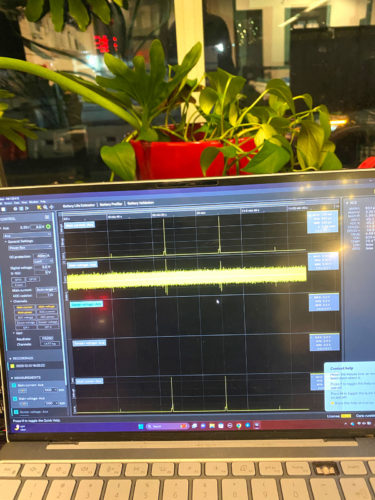
Now, using Qoitech’s Otii Ace Pro to accurately measure the power consumption, I confirm the following.
MAX: 136mA
AVG: 803µA
MIN: 550µA
So my new values are:
0.0005A during sleep
Averaging the active and transmit states:
0.04A *17/60 seconds= 0.011 A
0.136A * 3/60 seconds=0.0068 A
0.011A+0.0068 A=0.0178A for 20 seconds
Putting it all together:
Active: 0.0178A *20/1220 * 3.3V * 24 hours=0.023Wh
Sleep: 0.0005A *1200/1220 * 3.3V * 24 hours=0.038Wh
0.023Wh +0.38 Wh=~0.06 Wh per day
Sizing the System
Longevity is a crucial element of solar system design. When batteries fail, replacing them requires money, time, and human intervention: the more remote the deployment, the more challenging and costlier it is to replace the battery.
Remote sensor applications across agriculture, data collection, environmental monitoring, and asset tracking are generally expected to run for extended periods and, in some cases, need to run in extreme temperatures. As a solar system designer, you want your devices to continue running through various conditions (i.e., clouds, precipitation, or low and high temperatures)
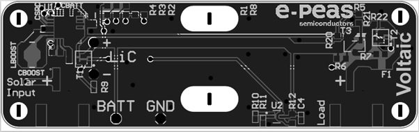
One solution available to you is Voltaic Systems’ Lithium-Ion Capacitor (LiC) based solar charger that incorporates the e-Peas AEM10941 Energy Harvester (https://voltaicsystems.com/LIC-solar-charger/) and the Vinatech hybrid capacitor. E-Peas is a leader in PMICs for energy harvesting, and the AEM10941 is an integrated energy management circuit that extracts DC power from up to 7-cell solar panels to simultaneously store energy in a rechargeable element and supply the system with an unregulated voltage output between 2.5 – 3.6V.
Lithium Ion Capacitors (LICs) are a great alternative to traditional lithium-ion batteries in many Low-power WAN (LPWAN) applications. The combination of high energy production solar panels (up to 300mW @1SUN) + High current PMIC (110mA) + High-capacity Storage (250F) makes this LiC exceptionally well suited to power connected nodes using LoRa and LTE CAT-M, and NB-IoT, or those using the Generic Node running on The Things Industries LoRaWAN network.

The LIC charges quickly. Even if completely discharged, the capacitor can be fully recharged in about 2 hours at full sun. The module can even work over periods of extended darkness. If your end device is low consumption, the module could theoretically run for a few months without access to the sun.
The Voltaic Systems’ LIC is an ultra-compact, lightweight, long-lifetime energy supply solution for heavy-duty applications that eliminates battery replacements and ensures performance across a range of temperatures (-40°C to 85°C).
For our device, we are going to add two 0.3 Watt 2 Volt ETFE laminate solar panels in parallel to charge the capacitor, which will provide an unregulated voltage between 2.5 – 3.8V—placing the panels in parallel increases the current but not the voltage. The Feather will run as long as the voltage is greater than 2.7V.
Connect positive leads from the panels to each other and negative leads to each other. Then, connect them to a JST to connect them to the capacitor.
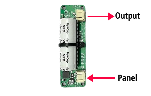
Connect the positive lead from the capacitor to the BAT input on the feather and the negative lead to GND.

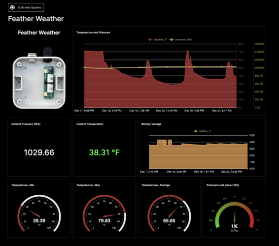
Connecting to a Dashboard
Now that the device is working and powered by solar, we need to connect it to a dashboard. A dashboard in an IoT context is not just a nice to have, but a crucial element of any IoT system. It enhances your IoT devices’ usability, management, and efficiency by providing a real-time view of your collected data.
For this example, we will use the Qubitro platform to visualize the temperature, pressure, and battery voltage. Qubitro provides tools and infrastructure to connect, manage, and scale IoT devices and has good documentation for getting started. Built to be device-agnostic, it can work with a wide variety of IoT devices regardless of manufacturer or protocols used.
Here is the complete code:
[code lang=”arduino”]/*******************************************************************************
* derived from The Things Network – Sensor Data Example
*
* Example of sending a valid LoRaWAN packet to The Things Networ using a Feather M0 LoRa.
*
* Learn Guide: https://learn.adafruit.com/the-things-network-for-feather
*
* Copyright (c) 2015 Thomas Telkamp and Matthijs Kooijman
* Copyright (c) 2018 Terry Moore, MCCI
* Copyright (c) 2018 Brent Rubell, Adafruit Industries
*
* Permission is hereby granted, free of charge, to anyone
* obtaining a copy of this document and accompanying files,
* to do whatever they want with them without any restriction,
* including, but not limited to, copying, modification and redistribution.
* NO WARRANTY OF ANY KIND IS PROVIDED.
*******************************************************************************/
#include <lmic.h>
#include <hal/hal.h>
/*#include */
#include <SPI.h>
#define uS_TO_S_FACTOR 1000 /* Conversion factor for microseconds to seconds */
#define TIME_TO_SLEEP 1200 /* Time feather will go to sleep (in seconds) */
#include "ArduinoLowPower.h"
#include <Adafruit_SleepyDog.h>
#include <Arduino.h>
#include <Wire.h>
#include <ArtronShop_SHT3x.h>ArtronShop_SHT3x sht3x(0x44, &Wire); // ADDR: 0 => 0x44, ADDR: 1 => 0x45
#define VBATPIN A7
static unsigned long previousMillis = 0;
unsigned long currentMillis;
unsigned long interval = 10000;
// This EUI must be in little-endian format, so least-significant-byte
// first. When copying an EUI from ttnctl output, this means to reverse
// the bytes. For TTN issued EUIs the last bytes should be 0xD5, 0xB3,
// 0x70.
static const u1_t PROGMEM APPEUI[8] = { 0x00, 0x00, 0x00, 0x00, 0x00, 0x00, 0x00, 0x00 };
void os_getArtEui(u1_t* buf) {
memcpy_P(buf, APPEUI, 8);
}
// This should also be in little endian format, see above.
static const u1_t PROGMEM DEVEUI[8] = { 0x79, 0x9D, 0x06, 0xD0, 0x7E, 0xD5, 0xB3, 0x70 };
void os_getDevEui(u1_t* buf) {
memcpy_P(buf, DEVEUI, 8);
}
// This key should be in big endian format (or, since it is not really a
// number but a block of memory, endianness does not really apply). In
// practice, a key taken from the TTN console can be copied as-is.
static const u1_t PROGMEM APPKEY[16] = { 0x31, 0x4E, 0xA4, 0x36, 0x2F, 0x49, 0x1E, 0x30, 0x43, 0x4D, 0x6E, 0xA5, 0x14, 0x3B, 0x02, 0xAE };
void os_getDevKey(u1_t* buf) {
memcpy_P(buf, APPKEY, 16);
}
// payload to send to TTN gateway
static uint8_t payload[7];
static osjob_t sendjob;
// Schedule TX every this many seconds (might become longer due to duty
// cycle limitations).
const unsigned TX_INTERVAL = 30;
// Pin mapping for Adafruit Feather M0 LoRa
// /!\ By default Adafruit Feather M0's pin 6 and DIO1 are not connected.
// Please ensure they are connected.
const lmic_pinmap lmic_pins = {
.nss = 8,
.rxtx = LMIC_UNUSED_PIN,
.rst = 4,
.dio = { 3, 6, LMIC_UNUSED_PIN },
.rxtx_rx_active = 0,
.rssi_cal = 8, // LBT cal for the Adafruit Feather M0 LoRa, in dB
.spi_freq = 8000000,
};
void printHex2(unsigned v) {
v &= 0xff;
if (v < 16)
Serial.print('0');
Serial.print(v, HEX);
}
void onEvent(ev_t ev) {
currentMillis = millis();
Serial.print(os_getTime());
Serial.print(": ");
switch (ev) {
case EV_SCAN_TIMEOUT:
Serial.println(F("EV_SCAN_TIMEOUT"));
break;
case EV_BEACON_FOUND:
Serial.println(F("EV_BEACON_FOUND"));
break;
case EV_BEACON_MISSED:
Serial.println(F("EV_BEACON_MISSED"));
break;
case EV_BEACON_TRACKED:
Serial.println(F("EV_BEACON_TRACKED"));
break;
case EV_JOINING:
Serial.println(F("EV_JOINING"));
break;
case EV_JOINED:
Serial.println(F("EV_JOINED"));
{
u4_t netid = 0;
devaddr_t devaddr = 0;
u1_t nwkKey[16];
u1_t artKey[16];
LMIC_getSessionKeys(&netid, &devaddr, nwkKey, artKey);
Serial.print("netid: ");
Serial.println(netid, DEC);
Serial.print("devaddr: ");
Serial.println(devaddr, HEX);
Serial.print("AppSKey: ");
for (size_t i = 0; i < sizeof(artKey); ++i) {
if (i != 0)
Serial.print("-");
printHex2(artKey[i]);
}
Serial.println("");
Serial.print("NwkSKey: ");
for (size_t i = 0; i < sizeof(nwkKey); ++i) {
if (i != 0) Serial.print("-");
printHex2(nwkKey[i]);
}
Serial.println();
} // Disable link check validation (automatically enabled // during join, but because slow data rates change max TX // size, we don't use it in this example. //LMIC_setLinkCheckMode(0); break; /* || This event is defined but not used in the code. No || point in wasting codespace on it. || || case EV_RFU1: || Serial.println(F("EV_RFU1")); || break; */ case EV_JOIN_FAILED: Serial.println(F("EV_JOIN_FAILED")); break; case EV_REJOIN_FAILED: Serial.println(F("EV_REJOIN_FAILED")); break; case EV_TXCOMPLETE: Serial.println(F("EV_TXCOMPLETE (includes waiting for RX windows)")); if (LMIC.txrxFlags & TXRX_ACK) Serial.println(F("Received ack")); if (LMIC.dataLen) { Serial.println(F("Received ")); Serial.println(LMIC.dataLen); Serial.println(F(" bytes of payload")); } // Schedule next transmission os_setTimedCallback(&sendjob, os_getTime() + sec2osticks(TX_INTERVAL), do_send); Serial.println("Going to sleep"); digitalWrite(LED_BUILTIN, LOW); LowPower.sleep(TIME_TO_SLEEP * uS_TO_S_FACTOR); digitalWrite(LED_BUILTIN, HIGH); break; case EV_LOST_TSYNC: Serial.println(F("EV_LOST_TSYNC")); break; case EV_RESET: Serial.println(F("EV_RESET")); break; case EV_RXCOMPLETE: // data received in ping slot Serial.println(F("EV_RXCOMPLETE")); break; case EV_LINK_DEAD: Serial.println(F("EV_LINK_DEAD")); break; case EV_LINK_ALIVE: Serial.println(F("EV_LINK_ALIVE")); break; /* || This event is defined but not used in the code. No || point in wasting codespace on it. || || case EV_SCAN_FOUND: || Serial.println(F("EV_SCAN_FOUND")); || break; */ case EV_TXSTART: Serial.println(F("EV_TXSTART")); break; case EV_TXCANCELED: Serial.println(F("EV_TXCANCELED")); break; case EV_RXSTART: /* do not print anything — it wrecks timing */ break; case EV_JOIN_TXCOMPLETE: Serial.println(F("EV_JOIN_TXCOMPLETE: no JoinAccept")); if (currentMillis – previousMillis > interval) {
previousMillis = currentMillis;
Serial.println("Going to sleep in one second…");
delay(1000);
// To enter low power sleep mode call Watchdog.sleep() like below
// and the watchdog will allow low power sleep for as long as possible.
// The actual amount of time spent in sleep will be returned (in
// milliseconds).
digitalWrite(LED_BUILTIN, LOW); // Show we're asleep
int sleepMS = Watchdog.sleep();
// Alternatively you can provide a millisecond value to specify
// how long you'd like the chip to sleep, but the hardware only
// supports a limited range of values so the actual sleep time might
// be smaller. The time spent in sleep will be returned (in
// milliseconds).
// int sleepMS = Watchdog.sleep(1000); // Sleep for up to 1 second.
// Code resumes here on wake.
digitalWrite(LED_BUILTIN, HIGH); // Show we're awake again
// Try to reattach USB connection on "native USB" boards (connection is
// lost on sleep). Host will also need to reattach to the Serial monitor.
// Seems not entirely reliable, hence the LED indicator fallback.
#if defined(USBCON) && !defined(USE_TINYUSB)
USBDevice.attach();
#endif
break;
}
break;
default:
Serial.print(F("Unknown event: "));
Serial.println((unsigned)ev);
break;
}
}
void do_send(osjob_t* j) {
// Check if there is not a current TX/RX job running
if (LMIC.opmode & OP_TXRXPEND) {
Serial.println(F("OP_TXRXPEND, not sending"));
} else {
// read the sensor
if (sht3x.measure()) {temperature = (9 * sht3x.temperature()) / 5 + 32;
Serial.print("Temperature: ");
Serial.print(temperature);
Serial.println(" *F");
// adjust for the f2sflt16 range (-1 to 1)
temperature = temperature / 100;// read the humidity from the DHT22
rHumidity = (sht3x.humidity());
Serial.print("%RH ");
Serial.println(rHumidity);
// adjust for the f2sflt16 range (-1 to 1)
rHumidity = rHumidity / 100;// note: this uses the sflt16 datum (https://github.com/mcci-catena/arduino-lmic#sflt16)
uint16_t payloadTemp = LMIC_f2sflt16(temperature);
// int -> bytes
byte tempLow = lowByte(payloadTemp);
byte tempHigh = highByte(payloadTemp);
// place the bytes into the payload
payload[0] = tempLow;
payload[1] = tempHigh;// float -> int
uint16_t payloadHumid = LMIC_f2sflt16(rHumidity);
// int -> bytes
byte humidLow = lowByte(payloadHumid);
byte humidHigh = highByte(payloadHumid);
payload[2] = humidLow;
payload[3] = humidHigh;} else {
Serial.println("SHT3x read error");
}
delay(1000);int readings = 1000;
float myReadings[readings];float v;
float sumV;for (int i = 0; i < readings; i++) {
myReadings[i] = analogRead(VOLT_PIN);
}
for (int j = 0; j < readings; j++) {
sumV += myReadings[j];
}
float averagedV = sumV / readings;
//float v = analogRead(VOLT_PIN);
float voltage = (averagedV * 3.3 / 4095) * 2.178;
/*b = val * 5 / 1024; //the math
b = val * (R1 + R2) / R2; //more math*/
float level;if (voltage >= 3.2 && voltage <= 4.2) {
level = map(voltage * 100, 3.2 * 100, 4.2 * 100, 0, 100);
} else if (voltage > 4.2) {
voltage = 4.2;
level = 100;
} else {
level = 0;
}Serial.print("voltage=");
Serial.println(voltage);
Serial.print("Level=");
Serial.println(level);voltage = voltage / 100;
level = level / 100;
// float -> int
uint16_t payloadV = LMIC_f2sflt16(voltage);
// int -> bytes
byte vLow = lowByte(payloadV);
byte vHigh = highByte(payloadV);
payload[4] = vLow;
payload[5] = vHigh;// float -> int
uint16_t payloadL = LMIC_f2sflt16(level);
// int -> bytes
byte lLow = lowByte(payloadL);
byte lHigh = highByte(payloadL);
payload[6] = lLow;
payload[7] = lHigh;// prepare upstream data transmission at the next possible time.
// transmit on port 1 (the first parameter); you can use any value from 1 to 223 (others are reserved).
// don't request an ack (the last parameter, if not zero, requests an ack from the network).
// Remember, acks consume a lot of network resources; don't ask for an ack unless you really need it.
LMIC_setTxData2(1, payload, sizeof(payload) – 1, 0);
}// Next TX is scheduled after TX_COMPLETE event.
}void setup() {
delay(5000);
Serial.begin(9600);
Serial.println(F("Starting"));
pinMode(LED_BUILTIN, OUTPUT);
digitalWrite(LED_BUILTIN, HIGH); // LMIC
init os_init(); // Reset the MAC state. Session and pending data transfers will be discarded.
LMIC_reset(); // Disable link-check mode and ADR, because ADR tends to complicate testing.
LMIC_setLinkCheckMode(0); // Set the data rate to Spreading Factor 7. This is the fastest supported rate for 125 kHz channels, and it // minimizes air time and battery power. Set the transmission power to 14 dBi (25 mW).
LMIC_setDrTxpow(DR_SF7, 14); // in the US, with TTN, it saves join time if we start on subband 1 (channels 8-15). This will // get overridden after the join by parameters from the network. If working with other // networks or in other regions, this will need to be changed. //comment this out?
LMIC_selectSubBand(1); // Start job (sending automatically starts OTAA too)
do_send(&sendjob);
}
void loop() {
// we call the LMIC's runloop processor. This will cause things to happen based on events and time. One
// of the things that will happen is callbacks for transmission complete or received messages. We also
// use this loop to queue periodic data transmissions. You can put other things here in the `loop()` routine,
// but beware that LoRaWAN timing is pretty tight, so if you do more than a few milliseconds of work, you
// will want to call `os_runloop_once()` every so often, to keep the radio running.
os_runloop_once();
}
[/code]
In conclusion, this tutorial offers a entry point into the world of IoT powered by This tutorial is an entry point into the world of solar-powered IoT. Programming and sizing your system are some of the practical aspects of designing energy-efficient remote data monitoring devices. Introducing the LIC demonstrates that a capacitor can provide a viable alternative to a battery for truly low-power devices. Using The Things Network and Qubitro dashboard brings an added dimension of network connectivity and data visualization to the project, making it a perfect blend of the practical IoT challenges you will face when designing your applications. Whether you’re a hobbyist, a student, or a professional, this tutorial provides valuable skills and knowledge applicable to a wide range of IoT applications, emphasizing the importance of efficient design.So what will you build?
- Navigate to the Arduino website.