
Overview:
Learn how to create a cloud-connected IoT device using an ESP32 connected to a DS18B20 temperature sensor temperature probe. In this tutorial, you will:
- Program your board using the Arduino IDE to send via WiFi temperature and battery voltage levels at certain times
- Reduce power consumption and consider ways to make the device more efficient
- Deploy system with appropriately sized solar panel and battery
- Publish data on the tago.io dashboard

An IoT ESP 32 Temperature Sensor
This tutorial will cover powering an ESP32 with a 6V solar panel and a 3.7V LiPo battery. It will also cover connecting the ESP32 to a network using WiFi and sending data to a cloud platform at regular intervals. Sending your data to a dashboard allows you to log and monitor sensor data over time and can be used for trends analysis and data-based decision-making. This type of remote monitoring system can be implemented in various fields, such as agriculture, environmental monitoring, and outdoor asset tracking.
This tutorial setup, from the parts to the dashboard, is relatively low-cost, making it accessible to anyone interested in getting started with setting up their own IoT devices. Ideally, this simple project will introduce you to sensors, coding, network communication, and cloud integration.
The dashboard we will be using in this tutorial is from TagoIO. TagoIO is a cloud IoT platform that is easy to connect to, use, and customize. In addition to being simple to set up, TagoIO provides free access to create five devices and five dashboards. This free level lets you immediately explore TagoIO’s dashboard capabilities. US-based TagoIO is used in over 120 countries and currently supports over 1000 different IoT applications across Agriculture, Buildings, Industrial, Energy, and Logistics verticals. Here’s a link to the dashboard in this tutorial.

Parts Needed
- ESP32 WROOM board
- Breadboard
- Wires
- ESP32 Breakout board
- Waterproof DS18B20 Temperature Sensor Temperature Probe
- 6 Volt Solar Panel
- Solar Panel Bracket – Medium
- Small Solar Ready Enclosure
- Adafruit Universal USB / DC / Solar Lithium Ion/Polymer charger – bq24074
- Lithium Ion Battery Pack – 3.7V 6600mAh
- 12V DC Power Connector 5.5mm x 2.1mm male
- Voltage divider for battery monitor:
Note that while there are a few versions of the ESP32 board, the board in this tutorial has 30 pins:

Several example circuits on the internet make use of the TP4056 Lithium Battery Charger Module, but these circuits require a voltage regulator — a Low-dropout or LDO regulator (MCP1700-3302E, a 100uF electrolytic capacitor, and a 100nF ceramic capacitor or a diode.
Besides needing additional components, there are better solutions than the TP4056 for a solar-powered circuit: Solar panels are not batteries. As a power source, they are unstable. Depending on the sunlight, the voltage and current a panel generates will vary according to the amount of light available. It is the fluctuations of voltage generated that can confuse battery chargers. When chargers are confused, they either rapidly turn on and off as they try to draw more current from the panel than possible, and/or they draw much less current than they can to keep the voltage from collapsing.
For this tutorial, I opted to go with the Adafruit Universal USB / DC / Solar Lithium Ion/Polymer charger – bq24074, which is designed to handle the variability of power from a solar panel. When the input drops below 4.5V, the charger backs off and automatically reduces the charge rate to keep the voltage above 4.5V.
Step 1: Gather Your Parts
Step 2: Pick a Breadboard Strategy
The ESP32 is not particularly breadboard-friendly. One solution is to use two breadboards and straddle the gap with the ESP32 or use a breakout board as I do.


Step 3: Wire the Circuit


The voltage divider for battery monitor logic comes from Random Nerd’s Power ESP32/ESP8266 with Solar Panels tutorial. The ESP32 has an input voltage of 3.3V, but the battery, when fully charged, outputs a higher voltage. By adding a voltage divider we are able to read the voltage level of the battery:

Voltage divider from Random Nerd’s tutorial
Code for reading battery level where b returns percentage and b2 returns voltage
[code lang=”arduino”] float val = analogRead(VOLT_PIN);
//reads the analog input
Serial.println(val);
Vout = (val * 3.3) / 4095.0; // formula for calculating voltage out
float b = Vout * (R2 + R1) / R2; // formula for calculating voltage in
b = map(val, 0.0f, 4095.0f, 0, 100);
float b2=(((b*40.95)*(3.3/4095))*4.2)/3.3;
[/code]
Step 4: Set Up the Arduino IDE
- Open or install the Arduino IDE. If you do not have the latest version of the Arduino IDE installed:
- Navigate to the Arduino website.
- Select your operating system and download the software.
- To program the ESP32 board using Arduino IDE, you need to install the ESP32 and add-on. Open the Preferences window in the Arduino IDE.
- Go to File > Preferences.
- Enter the following into the “Additional Board Manager URLs” field.
https://raw.githubusercontent.com/espressif/arduino-esp32/gh-pages/package_esp32_index.json
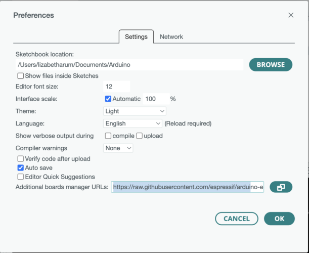
- Click OK.
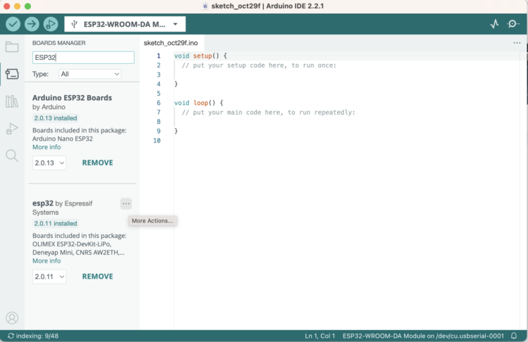
- Open the Boards Manager. Go to Tools > Board >Boards Manager…
- Search for ESP32 by Espressif Systems
Step 5: Set Up Your ESP32
Connect your ESP32-WROOM to your computer through USB. Then, follow these steps:
- Open the Arduino IDE.
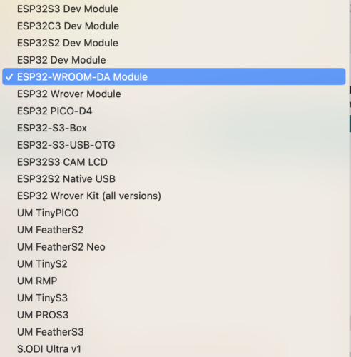
- Select your board in the Tools Board menu (in our case, it’s the ESP32-WROOM-DA Module).
- Select the Port. If you don’t see the COM Port in your Arduino IDE, you will need to install the ESP32 CP210x USB to UART Bridge VCP Drivers or other drivers, depending on the board model you’re using).
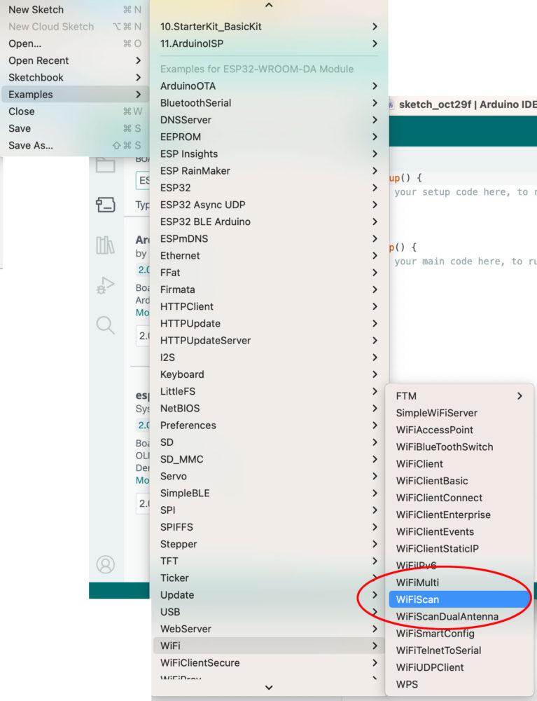
- To test that it all works, open the WiFi example:
- Click on the Upload button:
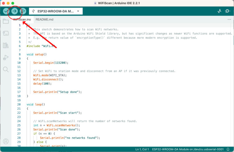
If everything went as expected, you should see a “Done uploading.” message. If you don’t, you’ll need to troubleshoot.
Step 6: Set Up Your Program
Create a new Sketch and save it as ESP32_temperature.
Step 7: Import Libraries
You’ll need a few libraries, so go to Tools and select Manage Libraries…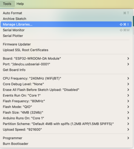
You’ll need to install:
- DallasTemperature by Miles Burton
- OneWire by Jim Studt, Tom Pollard, Robin James, and Paul Stoffregen
- ArduinoHttpClient by Arduino
- WifiMulti_Generic by Khoi Hoang
- ESPEssentials by Stephen Rumswinkel
When prompted, install all libraries and their dependencies.
Step 8: Copy and Paste the Code into Your Sketch
[code lang=”arduino”]// TagoIO and ESP integration with Temperature
// inspired by Carlo Stramaglia April 2nd 2023
#include <DallasTemperature.h>
#include <OneWire.h>
#include <HTTPClient.h>
#include <WiFi.h>
#include <sp_wifi.h>;
#define uS_TO_S_FACTOR 1000000ULL /* Conversion factor for micro seconds to seconds */
#define TIME_TO_SLEEP 10 /* Time ESP32 will go to sleep (in seconds) */
char serverAddress[] = "https://api.tago.io/data"; // TagoIO address
char contentHeader[] = "application/json";
char tokenHeader[] = "[XXX]"; // TagoIO Token
const char *ssid = "[XXX]";
const char *password = "[XXX]";
WiFiClient wifia;
// HttpClient client = HttpClient(wifia, serverAddress, port);
HTTPClient client;
int status = WL_IDLE_STATUS;
// Variables used in calculating the battery voltage
float b;
float Vout = 0.00;
float Vin = 0.00;
float R1 = 27000.00; // resistance of R1 (27K) // You can also use 33K
float R2 = 100000.00; // resistance of R2x (100K)
//int val = 0;
// GPIO where the DS18B20 is connected to
const int oneWireBus = 4;
const int VOLT_PIN = 33;
unsigned long startTime;
unsigned long timeAwake;
bool started=false;
// Setup a oneWire instance to communicate with any OneWire devices
OneWire oneWire(oneWireBus);
// Pass our oneWire reference to Dallas Temperature sensor
DallasTemperature sensors(&oneWire);
//Time in seconds
#define CONNECTION_TIMEOUT 5
#define DEEP_SLEEP_DURATION 10
void wifi_connect() {
WiFi.mode(WIFI_STA);
if (ssid != "")
WiFi.begin(ssid, password);
WiFi.begin();
Serial.println("");
// Wait for connection
int timeout_counter = 0;
while (WiFi.status() != WL_CONNECTED) {
Serial.print(".");
delay(100);
timeout_counter++;
if (timeout_counter >= CONNECTION_TIMEOUT * 10) {
Serial.println("\nCan't establish WiFi connexion");
//Setup timer
esp_sleep_enable_timer_wakeup(DEEP_SLEEP_DURATION * 1000000);
//Start deep sleep
esp_deep_sleep_start();
}
}
Serial.println("");
Serial.print("Connected to ");
Serial.println(ssid);
Serial.print("IP address: ");
Serial.println(WiFi.localIP());
}
void Read_And_Send_Sensors_Data() {
char anyData[30];
char postData[300];
char anyData1[30];
char bAny[30];
int statusCode = 0;
sensors.requestTemperatures();
Serial.print("Temperature in F: ");
Serial.println((sensors.getTempCByIndex(0) * 9.0) / 5.0 + 32.0); //print the temperature in Fahrenheit
float t = (sensors.getTempCByIndex(0) * 9.0) / 5.0 + 32.0;
//Temperature
Serial.print(F("Temperature: "));
Serial.println(t);
strcpy(postData, "{\n\t\"variable\": \"Temperature\",\n\t\"value\": ");
dtostrf(t, 6, 2, anyData);
strncat(postData, anyData, 100);
strcpy(anyData1, ",\n\t\"unit\": \"F\"\n\t}\n");
strncat(postData, anyData1, 100);
Serial.println(postData);
client.begin(serverAddress);
client.addHeader("Content-Type", contentHeader);
client.addHeader("Device-Token", tokenHeader);
statusCode = client.POST(postData);
// read the status code and body of the response
Serial.print("Status code: ");
Serial.println(statusCode);
Serial.println("End of POST to TagoIO");
Serial.println();
// Reading Battery Level
float val = analogRead(VOLT_PIN); //reads the analog input
Serial.println(val);
Vout = (val * 3.3) / 4095.0; // formula for calculating voltage out
b = Vout * (R2 + R1) / R2; // formula for calculating voltage in
float b = map(val, 0.0f, 4095.0f, 0, 100);
float b2=(((b*40.95)*(3.3/4095))*4.2)/3.3;
Serial.print(F("Battery Voltage: "));
Serial.println(b2);
strcpy(postData, "{\n\t\"variable\": \"Voltage\",\n\t\"value\": ");
dtostrf(b2, 6, 2, anyData);
strncat(postData, anyData, 100);
strcpy(anyData1, ",\n\t\"unit\": \"V\"\n\t}\n");
Serial.print(F("Battery Voltage: "));
Serial.println(b);
strcpy(postData, "{\n\t\"variable\": \"Voltage\",\n\t\"value\": ");
dtostrf(b, 6, 2, anyData);
strncat(postData, anyData, 100);
strcpy(anyData1, ",\n\t\"unit\": \"%\"\n\t}\n");
strncat(postData, anyData1, 100);
client.begin(serverAddress);
client.addHeader("Content-Type", contentHeader);
client.addHeader("Device-Token", tokenHeader);
statusCode = client.POST(postData);
// read the status code and body of the response
Serial.print("Status code: ");
Serial.println(statusCode);
Serial.println("End of POST to TagoIO");
Serial.println();
startTime=false;
}
void go_to_sleep() {
esp_sleep_enable_timer_wakeup(TIME_TO_SLEEP * uS_TO_S_FACTOR); // ESP32 wakes up every x seconds
Serial.println("Going to deep-sleep now");
startTime=false;
timeAwake=millis()-startTime;
Serial.print("Time Awake=");
Serial. println(timeAwake/1000.0);
Serial.flush();
esp_deep_sleep_start();
}
void setup() {
startTime=millis();
Serial.begin(115200);
delay(10);
wifi_connect();
}
void loop() {
wifi_connect();
Read_And_Send_Sensors_Data();
go_to_sleep();
}[/code]
Step 9: Create the Dashboard
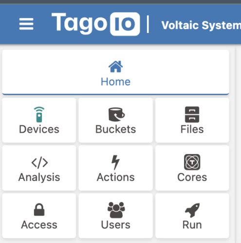
- Navigate to TagoIO and create an account or sign in.
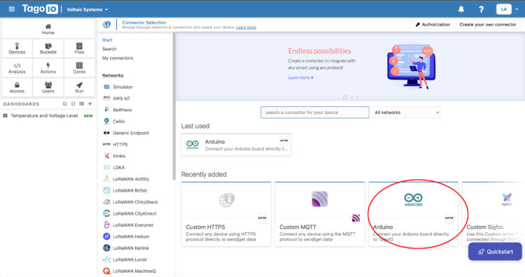
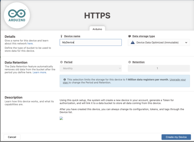
- Create a new device by clicking on the Device icon and then selecting the Arduino HTTP profile:
- Assign a name to your device and press the Create my Device button:
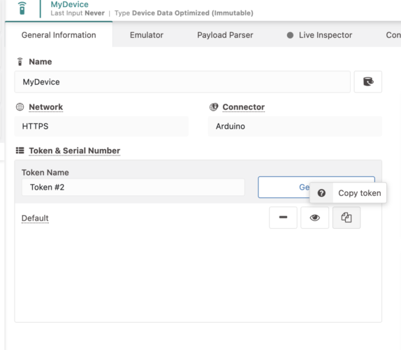
- Once the device is created, TagoIO will generate a token. Copy the token as you will need it in your Arduino code:
Step 10: Return to Arduino
- Back in the Arduino IDE, paste your token in this line and replace [XXX]
char tokenHeader[] = "[XXX]"; // TagoIO Token - Add your SSID name and password, replacing [XXX]:
[code lang=”arduino”]const char *ssid = "[XXX]";
const char *password = "[XXX]";[/code] - Compile and upload the code.
Step 11: Return to TagoIO
-
- Navigate back to TagoIO.
- Open the Live Inspector to check the data. You should see the temperature and battery level values posted in the TagoIO Interface.
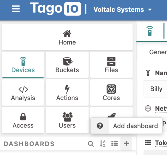
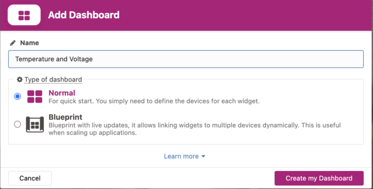
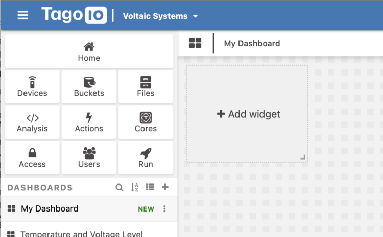
- Add a dashboard and name it:
- Name your dashboard and add a background:
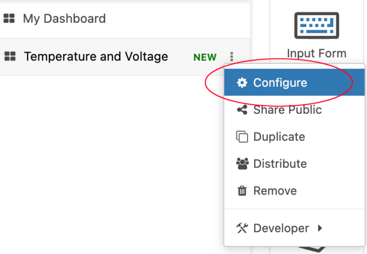
- Click on the three dots and select Configure:
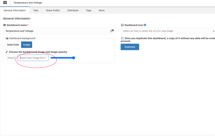
- You can add a background image to your dashboard here:
- Save and click on Add widget:
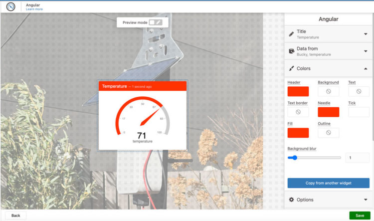
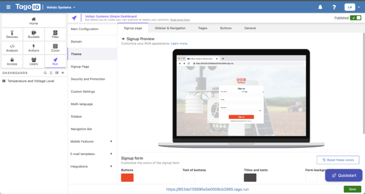
- Select a widget and format it. Give it a name and select the variable, change the colors, enable Show last update:
- Create a second widget for the Battery Voltage Level.
- If the values make sense, set your access by clicking on the Access button. Here, I have set access to be public:

- Set up your preferences in the Run tab:
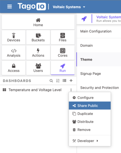
- Ctrl+click on the Dashboard name in the dashboards list and select Share Public if you want your dashboard to be public:
Step 12: Enable Deep_Sleep Mode
Now that everything is working, you’ll want to update the code to take advantage of deep sleep mode.
The use of deep_sleep mode in conjunction with solar power demonstrates efficient energy management. By sleeping most of the time and only waking up to read sensors and send data, you can minimize the energy consumption of your ESP32 device, which is crucial for battery longevity, especially when it relies on solar charging.
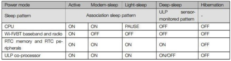
The ESP32 has the following operating modes:
- Active mode
- Modem Sleep mode
- Light Sleep mode
- Deep Sleep mode
- Hibernation mode
The following table lists which peripherals and units are either active or inactive during different modes.
Generally, the ESP32 is very power-hungry and may pull up to 75mA in normal consumption or inactive mode. If WiFi is also being used, then your current consumption could go up to somewhere around 240mA. If that’s the case, and you’re trying to power your device using batteries and solar, you won’t be able to use the ESP32 in active mode without draining your batteries.
There is a solution, and that is to put the module into a deep sleep mode to reduce the power consumption. When in deep sleep, the current consumption should be in the range of micro Amperes (μA) and your batteries will last longer.
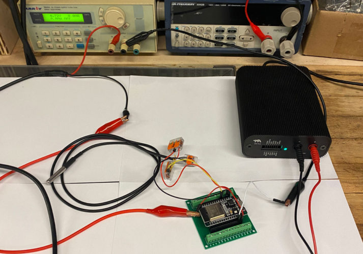
I tested my setup before implementing deep sleep mode using a Proshopping 150A RC Watt Meter, High Precision Power Analyzer attached to an external battery:
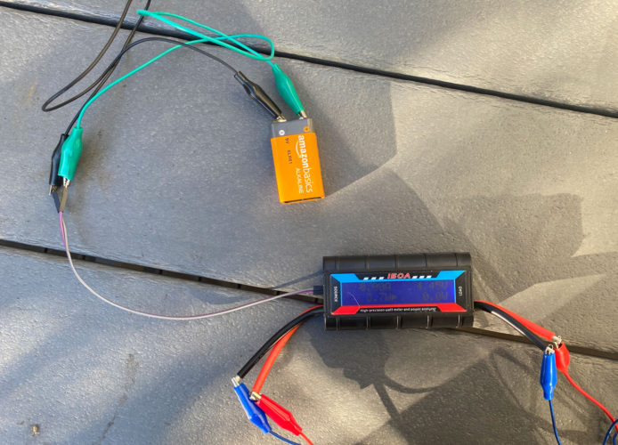
Inline setup with external battery connected
Here were my results when the ESP32 was sending data:
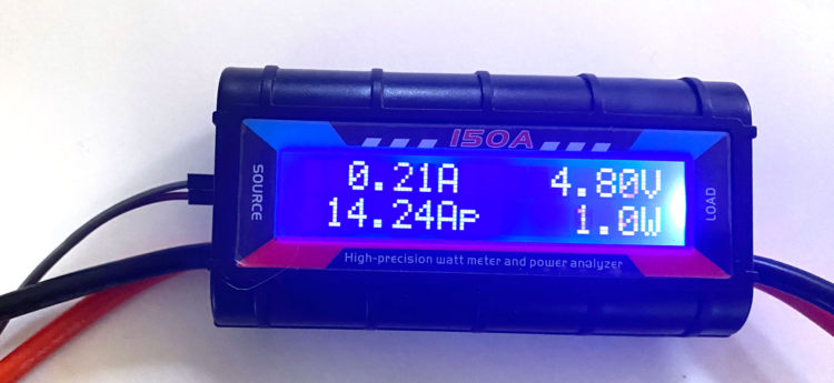
4.8V * 0.21A=.987 Wattor about 1 Watt. If I ran the program continually, it would consume 24 Watt hours per day (24hours * 1 Watt). In this semi-shady location, I expect the panel to produce closer to 5 Watt hours a day and if I don’t change anything, the system will fail. The solution is to send less data and put the device to sleep between transmission.The duty cycle is the ratio of time a load or circuit is ON compared to when the load or circuit is OFF. By manipulating this cycle, we can reduce the device’s power consumption.
The ESP32’s WiFi module, Processing Cores, and Bluetooth module all require current to operate. To conserve power, we can disable what we’re not using. Putting the ESP32 in deep_sleep mode disables everything except the RTC (Real Time Clock) module.
The power analyzer I’m using does not capture the current below .01A. So I can assume .01A in the worst case, but from the documentation, I know I’m in the micro Amperes range. If I use the timer in the code to measure how many seconds the device needs to take a measurement and send the data and then enable deep_sleep for a certain amount of time in between waking, reading, and sensing, I can conserve quite a bit of power.
If the device needs around 5-10 seconds to connect to WiFi, read and send the data, and is in deep_sleep mode for 10 minutes in between readings, then the device is on for about 2 minutes every hour and in deep_sleep for the rest of the hour.
Deep_sleep Power Consumption
[code lang=”arduino”]4.7V * 0.01A = ~0.047 Watts
proportion of time device is sleeping = 59/60
59/60 * 0.047 Watts = 0.0462 Watts
0.0462 Watts * 24h/day = 1.108 Watt hours per day in sleep mode[/code]Reading and Sending Power Consumption
[code lang=”arduino”]4.7V * 0.21A = ~1 Watt
proportion of time device is awake = 1/60
1/60 * 1 Watt = 0.0166 Watts
0.0166 Watts * 24h/day =0.3983 Watt hours per day reading and sending[/code]
So guesstimating my consumption this way brings it down to about 0.066Wh.If I multiply that number by 24, I end up with 1.58Wh a day.
Total Power Consumption
[code lang=”arduino”](1/60)*0.21A + (59/60)*0.01A = 0.0133A
0.0035 + 0.0098 = 0.0133A
4.7V * 0.0133A = 0.0625Wh
24 * .0625Wh = ~1.5Wh[/code]Implementing deep_sleep brings the power consumption down from 24Wh to about 1.5Wh. That’s a big difference!
The method above was a rough estimation. If I use Qoitech’s Otii Ace Pro, I can more accurately measure the power consumption.
Here is the circuit attached inline to the Qoitech:
And here are the results:
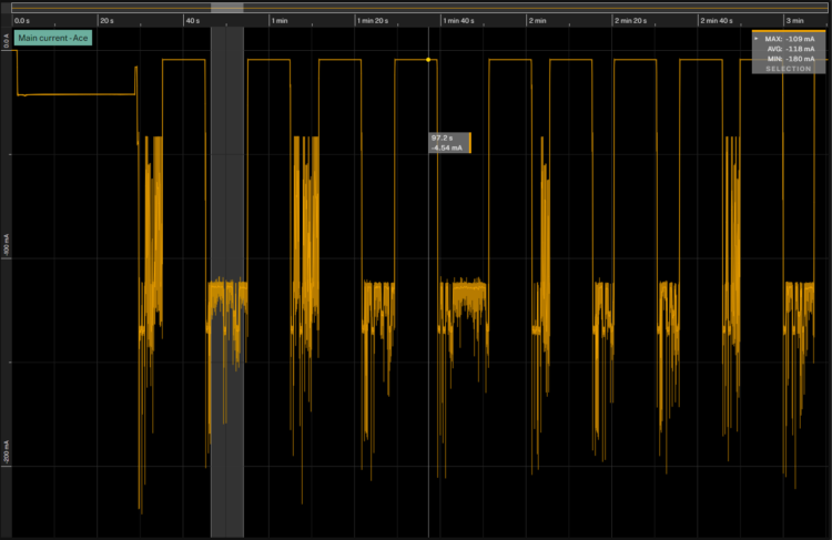
From the readings, I can see that when the device is awake, sensing, and sending, the amps measured equal a max of 180mA or .18A. When the device is in deep_sleep mode, the amps measured are 4.54mA or 0.00454A.
[CP_CALCULATED_FIELDS id=”7″]
Return to your code and update this line:
#define TIME_TO_SLEEP 30 /* Time ESP32 will go to sleep (in seconds) */Think about how often you really need to check the temperature. Every 15 minutes, 30 minutes, hour? Play with the form above and then make your adjustments to your code.
While I started with a panel and battery, if you were building your own device from scratch, you would want to create your circuit without the panel or battery. You would then measure your power consumption with a watt meter, Qoitech, or similar. You would then select your panel and device based on:
- your estimated daily power consumption
- where your device is deployed
- how much sun your device will be exposed
- how many days you would expect your device to run without sun.
Leave a Reply