
Overview
This blog post is a step-by-step walkthrough to run a Nano 33 IoT application from solar power. You will learn about:
- Managing power consumption on an Arduino Nano 33 IoT
- Converting RS485 data to serial
- Publishing data on the Qubitro IoT platform
- Monitoring system health of a solar powered application

Whether you’re a hobbyist, educator, or professional, this POC demonstrates the potential of solar-powered IoT solutions and the ease with which they can be implemented to address real-world challenges.
Parts Needed
- Arduino® Nano 33 IoT with headers
- 5 Watt 5 Volt 35Wh Solar System
- Renkeer RS-SD-N01-TR- Soil moisture sensor
- RS-485 Converter Module TTL to RS-485 Adapter
- USB 2.0 Pigtail 4 Wire
- Wires
- For lowering power consumption with a RTC
- Adafruit DS3231 Precision RTC Breakout
- 1x resistor 10kOhms
- 1x resistor 100Ohms
- IRF9520 P-channel MOSFET
- Pololu S7V7F5 voltage regulator
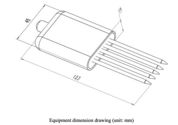
The Renke Soil Moisture Sensor
The sensor measures the dielectric constant of soil and the volume percentage of soil moisture, which is a soil moisture measurement method in line with current international standards. You can bury it in the soil for a long time, as the electrode is made of alloy material, it is durable, waterproof, and resistant to long-term electrolysis, acid and alkali corrosion.
The sensor is suitable for soil moisture monitoring, scientific experiments, water-saving irrigation, greenhouses, flowers and vegetables, grassland pastures, soil rapid testing, plant cultivation, sewage treatment, precision agriculture and other occasions temperature and humidity, conductivity, PH value testing .
It can be powered by 4.5-30V and operates between -20°C to ~60°C.
Here are some best practices for using the sensor:
- The steel needles must be fully inserted into the soil when measuring.
- Avoid direct sunlight on the transmitter that will cause the temperature to be too high. Pay attention to lightning protection when using in the field.
- Do not bend the steel needles violently, do not pull the lead wire of the transmitter forcibly, and do not violently hit the transmitter.
- The protection level of the transmitter is IP68, and the entire transmitter can be soaked in water.
- Due to the existence of radio frequency electromagnetic radiation in the air, it is not suitable to be energized in the air for a long time.
- It should be calibrated before each measurement. It is recommended to calibrate every 1 month for long-term use. The calibration frequency should be adjusted according to different application conditions (soil quality, moisture content, salt content, pH, etc. of the application)

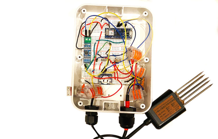
Wiring Instructions
| Color | Function |
|---|---|
| Brown | V+ |
| Black | GND |
| Yellow | RS485-A |
| Blue | RS485-B |
Modbus Communication of the Soil Sensor
Here are the specific configurations for the soil sensor that define how data is formatted, transmitted, and checked for errors in Modbus communication:
- 8 bit binary
- Parity bit= none
- Stop bit= 1
- Error checking – CRC
- Baud rate = default 4800
The following refers to specific Modbus register addresses in hexadecimal format and their associated data points for the soil sensor:
Address code=0x01 — the address of the peripheral device
Register address= 0x00 0x9C41 -moisture content
Register address= 0x01 0x9C42 -temperature
Register address= 0x02 0x9C43 -Conductivity
Register address= 0x03 0x9C44 -pH value
Register address= 07D0 0xA411 -Device Address
Register address= 07D1 0xA412 -Device Baud Rate
| Command | Baud Rate |
|---|---|
| 0 | 2400 |
| 1 | 4800 |
| 2 | 9600 |
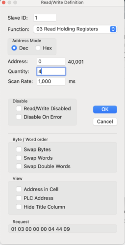
You can test this out in a program like ModbusRTUmaster to read moisture, temperature, conductivity, and PH value of the four-in-one device (address 0x01).
0x01 0x03 0x00 0x00 0x00 0x04 0x44 0x09
Here are some helpful details about the results:
Temperature calculation:
When the temperature is lower than 0 °C, the temperature data is uploaded in the form of complement code.
Temperature:
FF9B H(hex) = -101 => temperature = -10.1°C
Moisture calculation:
292 H (Hex) = 658 => Humidity = 65.8%, that is, the soil volume moisture content is 65.8%.
Conductivity calculation:
3E8 H (hex) = 1000 Conductivity = 1000 us/cm
PH value calculation:
38H (hexadecimal) = 56 => PH value = 5.6
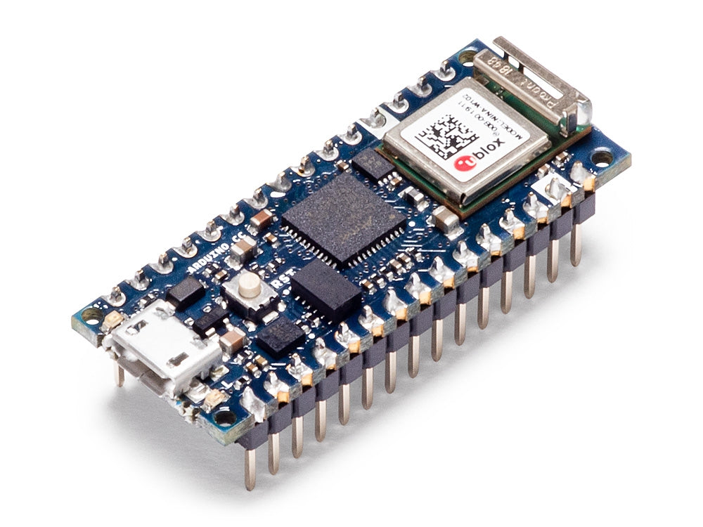
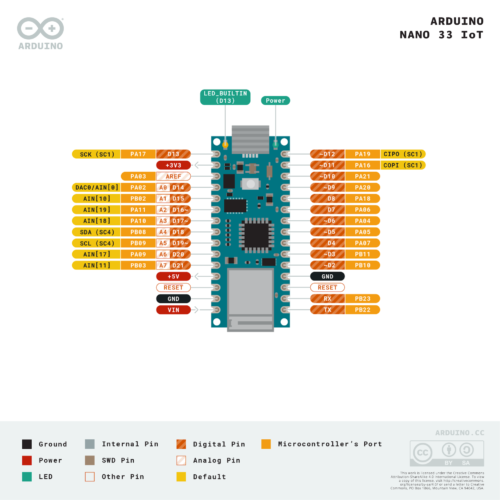
The Arduino Nano 33 IoT
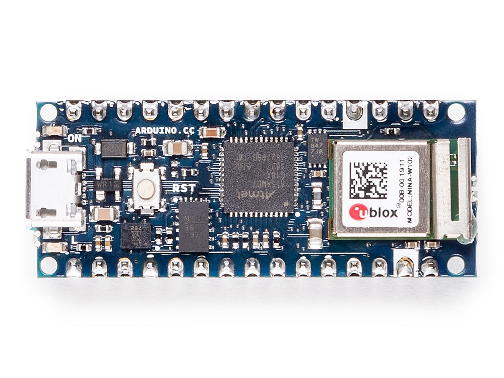
The Arduino Nano 33 IoT can be powered by the USB connector (5V) or through the Vin pin (4.5V – 21V). Its operating voltage is 3.3V.
Saving Power
Here are two recommended approaches to save power with the Arduino Nano 33 IoT (We’ll be taking the second approach):
- See how to put the Arduino Nano 33 IoT on sleep.
- See how to shut down the power of the Arduino Nano 33 IoT and wake up on a specific time with the RTC.
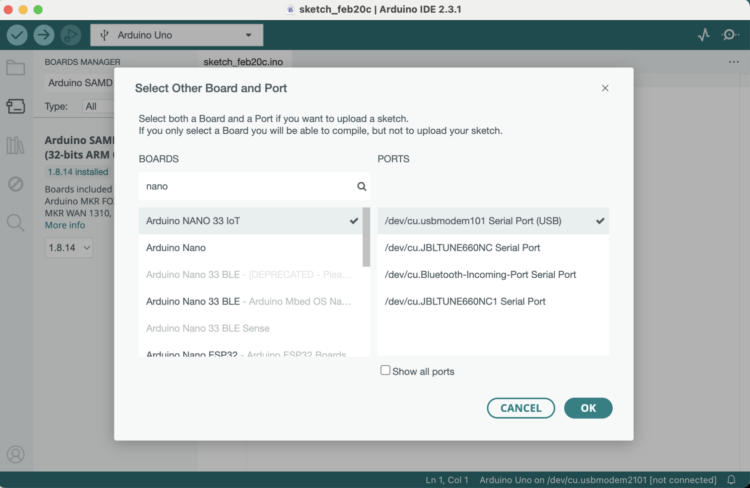
Setting up the Arduino Nano 33 IoT
- Open the Arduino IDE
- Create a new Sketch
- Under Boards, add the Arduino SAMD Boards
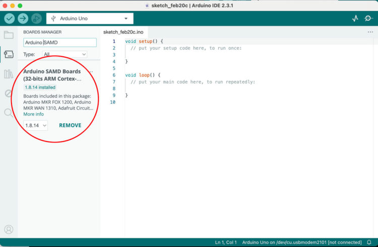
- Select the board and port by clicking on the triangle in the box next to the debug icon:
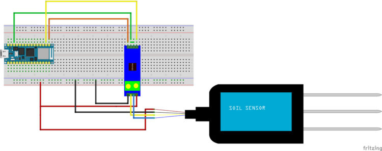
Setting up the MAX 485 TTL to RS485 Converter Module
Here is some guidance for connecting the Max 485 to the Arduino to the Soil Sensor
| Max 485 | Description | Arduino | Soil Sensor |
|---|---|---|---|
| VCC | 3.3 to 5V | USB | 5V (Brown) |
| GND | Ground | GND | GND (Black) |
| A | RS485 A (Driver Output) | Yellow Wire | |
| B | RS485 B (Driver Output) | Blue Wire | |
| RO | Receiver Output | RX (0) | |
| DE | Driver Enable Input | 10 | |
| RE | Receiver Enable Input | 10 | |
| DI | Driver Input | TX (1) |
- Wire up the circuit:
- Tie RE to DE with a small wire
- Connect RO to RX
- Connect DI to TX
- Connect Ground to common GND
- Connect VCC to the V35 5V
- Connect RS485 DATA B to Soil Sensor Blue
- Connect RS485 DATA A to Soil Sensor Yellow
- Soil Sensor Brown to V35 5V
- Soil Sensor Black to GND
- In the Arduino IDE add the following library:ModbusMaster by Doc Walker
- Make sure that the Nano 33 IoT board and USB port are selected.
- The function we are interested in is
[code] 0x03 – Read Holding Registers:readHoldingRegisters(uint16_t u16ReadAddress, uint16_t u16ReadQty);[/code]
Copy and paste this code into the Sketch:
[code lang=”arduino”]// github link: https://github.com/4-20ma/ModbusMaster
#include <ModbusMaster.h>
/* Modbus stuff */
#define MODBUS_DIR_PIN 10 // connect DR, RE pin of MAX485 to gpio 10
#define MODBUS_RX_PIN 0 // Rx pin
#define MODBUS_TX_PIN 1 // Tx pin
#define MODBUS_SERIAL_BAUD 4800 // Baud rate for max485 communication//Initialize the ModbusMaster object as node
ModbusMaster node;
float moisture, pH, conductivity, temperature;// Pin 10 made high for Modbus transmision mode
void modbusPreTransmission() {
delay(500);
digitalWrite(MODBUS_DIR_PIN, HIGH);
}// Pin 10 made low for Modbus receive mode
void modbusPostTransmission() {
digitalWrite(MODBUS_DIR_PIN, LOW);
delay(500);
}void setup() {
// serial communication
Serial.begin(9600);
pinMode(MODBUS_DIR_PIN, OUTPUT);
digitalWrite(MODBUS_DIR_PIN, LOW);//Serial1.begin(baud-rate, protocol, RX pin, TX pin);.
Serial1.begin(MODBUS_SERIAL_BAUD);
//modbus slave ID 1
node.begin(1, Serial1);// callbacks allow us to configure the RS485 transceiver correctly
node.preTransmission(modbusPreTransmission);
node.postTransmission(modbusPostTransmission);}
void loop() {
uint8_t result;//Modbus function 0x03 Read Holding Registers
result = node.readHoldingRegisters(0, 4);if (result == node.ku8MBSuccess) {
Serial.println("Success, Received data: ");
Serial.print("Moisture: ");// we just convert the uint16_t type data array to float type using type casting
moisture = float(node.getResponseBuffer(0)) * 0.1f;
temperature = float(node.getResponseBuffer(1)) * 0.1f;
conductivity = float(node.getResponseBuffer(2));
pH = float(node.getResponseBuffer(3)) * 0.1f;
Serial.print("Moisture: ");
Serial.print(moisture);
Serial.println("%");
Serial.print("Temperature: ");
temperature = (temperature * 9) / 5 + 32;
Serial.print(temperature);
Serial.println("°F");
Serial.print("Conductivity: ");
Serial.print(conductivity);
Serial.println("us/cm");
Serial.print("pH value: ");
Serial.println(pH);
}else {Serial.print("Failed, Response Code: ");
Serial.print(result, HEX);
Serial.println("");
delay(5000);
}
delay(1000);}[/code]
- Here are the error codes..
If you get an error, make sure:- Your wires are connected properly
- Your sensor is receiving enough power
- Your sensor is in the dirt
Power Consumption
We still need to put the board to sleep to conserve power. In order to keep our project alive for months/years on the battery/panel strategy, we need to minimize our power consumption. Below you will find two approaches (I’ll be using the second approach).
Approach One: ArduinoLowPower with N-Channel MOSFET
The Arduino Nano 33 IoT can be put into various sleep modes to reduce power consumption. The ArduinoLowPower library is one way to put the board into idle or deep sleep modes. We’ll also need to turn off the sensor. One strategy for turning off the sensor is to use an N-channel mosfet.
Here’s the pseudocode:
- Turn off the sensor
- Shutdown power during sleep cycle
- Wake up the board at a predefined interval
- Turn on the sensor
Parts Needed:
- 1x resistor 10kOhms
- IRFZ44N N-channel MOSFET
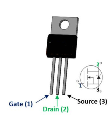
- Wire up the circuit with an N-Channel MOSFET. I’m using an IRFZ44N Mosfet. An N-Channel Mosfet allows us to connect the GNDs of the sensors and board together.
- Place a 10KΩ resistor between the Gate (pin 1) and the Source (pin 3).
- Pull the Source (pin 3) down by connecting it to GND.
- Connect the Drain (pin 2) to the ground of the MAX 485 module.
- Connect the Gate (pin 1) to Nano D2.
When adding sleep functions, add a long delay in the setup() function so that you have an opportunity to reprogram the board. Just reset the board to initiate the setup() function.
- Adjust your code:
- Include the Arduino Low Power library
- Add an instance variable for the transistor pin:
[code]int transistorPin=2;[/code]
- Add another variable called counter. This will keep track of how many times we poll the sensor before calling a sleep function
[code]int counter=0;[/code]
- Add another variable named
secondsof type int and set it to 30:[code]int seconds=30;[/code]
- Add a long delay in setup():
[code]delay(5000);[/code]
- Set the pin to an OUTPUT in setup() and set it to LOW:
[code lang=”arduino”]pinMode(transistorPin, OUTPUT);
digitalWrite(transistorPin, LOW);
[/code] - Set counter to 0:
[code]counter=0;[/code]
- Set the transistorPin HIGH after you connect to the Arduino Cloud. You can do that by adding the line
digitalWrite(transistorPin, HIGH);afterArduinoCloud.begin(ArduinoIoTPreferredConnection);insetup() - In loop, nest the sensor code in a conditional that runs if
counter<5. - At the end of the conditional, increment
counterby 1. - If the condition is not met, call this function:
callForSleep() - Create a
callForSleep()function - Inside the
callForSleep()set the transistor pin to low before you call the sleep function:digitalWrite(transistorPin,LOW);
- Call sleep after setting the transistorPin
LOWLowPower.deepSleep(seconds * 1000);
- Call
setup()
Approach Two: RTC and P-Channel MOSFET
This second strategy involves a RTC module and P-channel mosfet. This strategy basically does the following (you can find more information in Olivier Staquet’s Arduino-Nano-33-IoT-Ultimate-Guide):
- Shutdowns all the power of the circuit during the sleep cycle
- Wakes up the microcontroller at a predefined interval (every minute, every hour, every day or at a specific moment).
- Consumes only the power required for the RTC clock
Parts Needed:
- Adafruit DS3231 Precision RTC Breakout
- 1x resistor 10k Ohms
- 1x resistor 100 Ohms
- IRF9520 P-channel MOSFET
- Pololu S7V7F5 voltage regulator
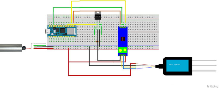
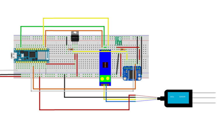
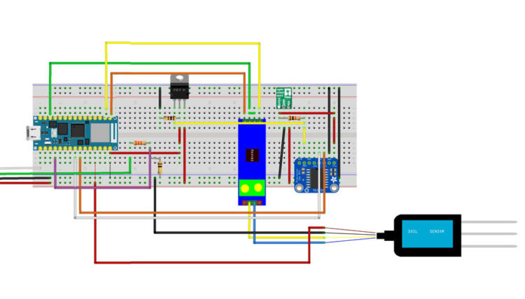
- Wire up this circuit
- Add the DS3231, Voltage Regulator, and MOSFET to your breadboard
- DS3231 connections
- Connect VIN to VOUT of your Voltage Regulator
- Connect GND to common ground
- Connect SCL to Nano A5
- Connect SDA to Nano A4
- Connect SQW to MOSFET Gate (pin 1)
- Connect SQW to VOUT of your Voltage Regulator through a 10KΩ Resistor
- Voltage Regulator connections
- Connect GND to common ground
- Connect VIN to 5V
- MOSFET connections
- Connect Drain (pin 2) to common ground through a 100Ω Resistor
- Connect Drain (pin 2) to Nano VIN
- Connect Source (pin 3) to 5V
https://github.com/ostaquet/Arduino-Nano-33-IoT-Ultimate-Guide/blob/master/SavePowerRTC.md
- Download and install library DS3231 by NothernWidget
- Include the DS3231 library in your sketch.
- Add the following to the top of your sketch:
[code lang=”arduino”]
#include <Wire.h>
#include <DS3231.h>
#include <SPI.h>
[/code] - Add this global variable:
[code lang=”arduino”]
DS3231 Clock;
[/code] - In
setup()beforeSerial.begin(), set up the RTC:[code lang=”arduino”]
// Start the I2C interfaceWire.begin();
// Initialize the RTC clock
// Disable alarm
Clock.turnOffAlarm(2);
// Disable oscialltor
Clock.enableOscillator(false, false, 0);
// Disable 32kHz output
Clock.enable32kHz(false);
// Set in 24-hour mode
Clock.setClockMode(false);
[/code] - Before the end of setup(), add the following:
[code lang=”arduino”]
// Prepare the next execution (defined by the day, hour, minute, second) + interval
// Interval:
// 0b1111 // each second
// 0b1110 // Once per minute (when second matches)
// 0b1100 // Once per hour (when minute and second matches)
// 0b1000 // Once per day (when hour, minute and second matches)
// 0b0000 // Once per month when date, hour, minute and second matches. Once per week if day of the week and A1Dy=true
// Set alarm to happen every minute (change to your wanted interval)// Every time the seconds match 4 (every minute at the 4th second, the system wakes up)
Clock.setA1Time(1, 2, 3, 4, 0b1110, false, false, false);Clock.turnOnAlarm(1);
// Empty the I2C buffer
while (Wire.available()) {
Wire.read();}
[/code] - In your loop() function find these lines:
[code lang=”arduino”]
} else {
Serial.print("Failed, Response Code: ");
Serial.print(result, HEX);
Serial.println("");
delay(5000);
}
[/code] - Paste in the following after the else closes:
[code lang=”arduino”]
// End doing something
// Reset alarm is the last instruction of the program
// When we reset the alarm, the power is shutdown for the system
Clock.checkIfAlarm(1);// We never arrive here because the alarm is cleared
// on the RTC which cause the shutdown of the circuit
while (1)
;[/code] - Verify and Upload
- Disconnect from the computer to test.
- When satisfied with the code, reconnect and change to wake up every hour.
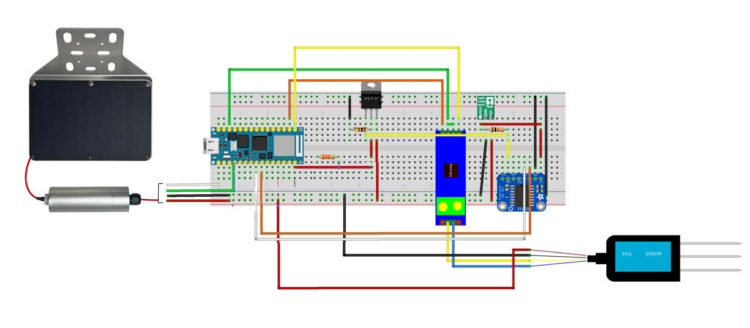
Here is the complete circuit diagram:
Connecting to Wi-Fi
If we want to connect to a publish dashboard, we’ll have to modify our code a bit.
The Nano 33 IoT’s embedded Wifi module is the NINA W102 ESP32 based module. It provides support of Wifi 802.11 b/g/n in the 2.4 GHz band and Bluetooth v4.2 (Bluetooth BR/EDR and Bluetooth Low Energy BLE). The module is fully compatible with the official WiFiNINA library.
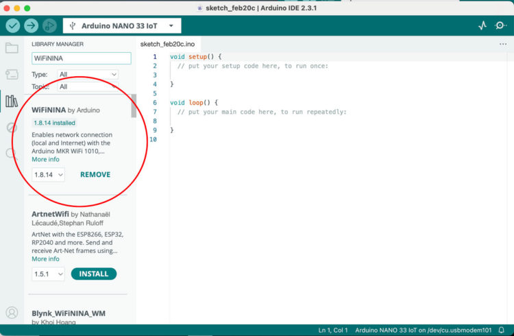
- Open a new Sketch.
- To install the WiFiNINA by Arduino library in the Arduino IDE. Click on the library icon on the left side, search for WifiNINA and click the INSTALL button to install the library:
- Replace the current sketch with:
[code lang=”arduino”]/*
WiFi Web Server LED Blink
A simple web server that lets you blink an LED via the web.
This sketch will print the IP address of your WiFi module (once connected)
to the Serial Monitor. From there, you can open that address in a web browser
to turn on and off the LED on pin 9.
If the IP address of your board is yourAddress:
http://yourAddress/H turns the LED on
http://yourAddress/L turns it off
This example is written for a network using WPA encryption. For
WEP or WPA, change the WiFi.begin() call accordingly.
Circuit:
* Board with NINA module (Arduino MKR WiFi 1010, MKR VIDOR 4000 and Uno WiFi Rev.2)
* LED attached to pin 9
created 25 Nov 2012
by Tom Igoe
*/
#include <SPI.h>
#include <WiFiNINA.h>
#include "arduino_secrets.h"
///////please enter your sensitive data in the Secret tab/arduino_secrets.h
char ssid[] = SECRET_SSID; // your network SSID (name)
char pass[] = SECRET_PASS; // your network password (use for WPA, or use as key for WEP)
int keyIndex = 0; // your network key index number (needed only for WEP)
int status = WL_IDLE_STATUS;
WiFiServer server(80);
void setup() {
Serial.begin(9600); // initialize serial communication
pinMode(LED_BUILTIN, OUTPUT); // set the LED pin mode
// check for the WiFi module:
if (WiFi.status() == WL_NO_MODULE) {
Serial.println("Communication with WiFi module failed!");
// don't continue
while (true);
}
String fv = WiFi.firmwareVersion();
if (fv < WIFI_FIRMWARE_LATEST_VERSION) {
Serial.println("Please upgrade the firmware");
}
// attempt to connect to WiFi network:
while (status != WL_CONNECTED) {
Serial.print("Attempting to connect to Network named: ");
Serial.println(ssid); // print the network name (SSID);
// Connect to WPA/WPA2 network. Change this line if using open or WEP network:
status = WiFi.begin(ssid, pass);
// wait 10 seconds for connection:
delay(10000);
}
server.begin(); // start the web server on port 80
printWifiStatus(); // you're connected now, so print out the status
}
void loop() {
WiFiClient client = server.available(); // listen for incoming clients
if (client) { // if you get a client,
Serial.println("new client"); // print a message out the serial port
String currentLine = ""; // make a String to hold incoming data from the client
while (client.connected()) { // loop while the client's connected
if (client.available()) { // if there's bytes to read from the client,
char c = client.read(); // read a byte, then
Serial.write(c); // print it out to the serial monitor
if (c == '\n') { // if the byte is a newline character
// if the current line is blank, you got two newline characters in a row.
// that's the end of the client HTTP request, so send a response:
if (currentLine.length() == 0) {
// HTTP headers always start with a response code (e.g. HTTP/1.1 200 OK)
// and a content-type so the client knows what's coming, then a blank line:
client.println("HTTP/1.1 200 OK");
client.println("Content-type:text/html");
client.println();
// the content of the HTTP response follows the header:
client.print("Click <a href=\"/H\">here</a> turn the BUILTIN LED on<br>");
client.print("Click <a href=\"/L\">here</a> turn the BUILTIN LED off<br>");
// The HTTP response ends with another blank line:
client.println();
// break out of the while loop:
break;
} else { // if you got a newline, then clear currentLine:
currentLine = "";
}
} else if (c != '\r') { // if you got anything else but a carriage return character,
currentLine += c; // add it to the end of the currentLine
}
// Check to see if the client request was "GET /H" or "GET /L":
if (currentLine.endsWith("GET /H")) {
digitalWrite(LED_BUILTIN, HIGH); // GET /H turns the LED on
}
if (currentLine.endsWith("GET /L")) {
digitalWrite(LED_BUILTIN, LOW); // GET /L turns the LED off
}
}
}
// close the connection:
client.stop();
Serial.println("client disconnected");
}
}
void printWifiStatus() {
// print the SSID of the network you're attached to:
Serial.print("SSID: ");
Serial.println(WiFi.SSID());
// print your board's IP address:
IPAddress ip = WiFi.localIP();
Serial.print("IP Address: ");
Serial.println(ip);
// print the received signal strength:
long rssi = WiFi.RSSI();
Serial.print("signal strength (RSSI):");
Serial.print(rssi);
Serial.println(" dBm");
// print where to go in a browser:
Serial.print("To see this page in action, open a browser to http://");
Serial.println(ip);
}[/code] - Create a new tab and name it arduino_secrets.h. Then add the following and include your network (yourssid) and password (yourpasswd):
[code lang=”arduino”]#define SECRET_SSID "yourssid"
#define SECRET_PASS "yourpasswd"
[/code] - Upload, open the Serial monitor, and then follow the instructions to test.
Connecting to a Public Dashboard – Qubitro
For our public dashboard, we’ll use Qubitro and the MQTT protocol.
MQTT is a lightweight application layer messaging protocol designed for resource-constrained devices used for IoT applications. It utilizes a topic-based, publish-subscribe, or Pub/Sub model where the protocol defines how IoT devices can publish and subscribe to data over the Internet. There is a sender (Publisher) and a receiver (Subscriber) and they communicate by topics.
MQTT is the most commonly used messaging protocol for IoT because:
- It is lightweight and efficient- Its small code footprint and minimal network bandwidth usage enable efficient communication even in constrained environments
- Low power consumption – This makes it suitable for battery-operated IoT devices, such as sensors and actuators, that need to conserve power to extend battery life<
- Easy to implement and has numerous libraries and associated tools
- Supports bi-directional messaging between device and cloud
- Can scale easily to handle a large number of devices
- Can support levels of reliable message delivery – the three levels of Quality of Service allow developers to balance between overhead and the importance of message delivery guarantees
- Works well over unreliable networks- the Pub/Sub model makes it suitable for IoT devices that might be operating on limited data plans or in areas with poor network connectivity.
- Works with TLS/SSL and common authentication protocols
Before we can send data, we need to create a new MQTT source at Qubitro.
- Create an account or log into your Qubitro account.
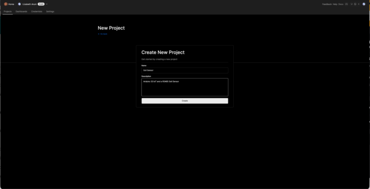
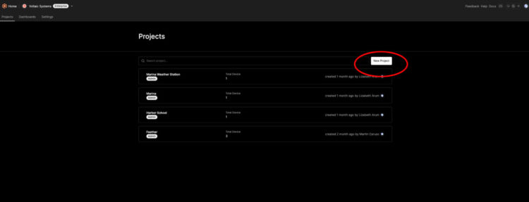
- Create a New Project:
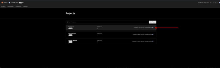
- Add the details to your project and click on the Create button:
- Select the project:
- On the project detail page, click on the New Source button:
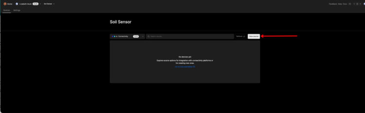
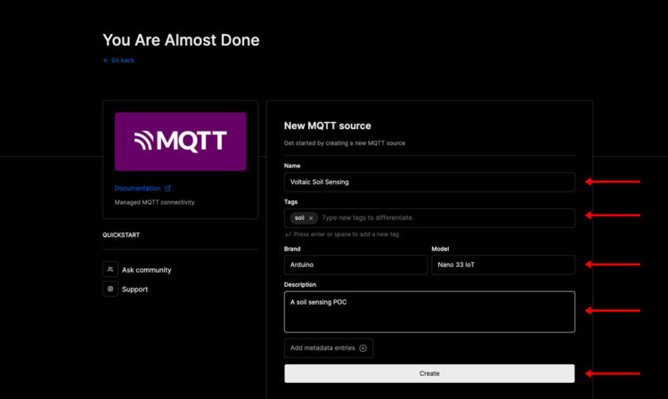
- Select MQTT:

- Complete the details:
- Click on the project again and select Connection details:
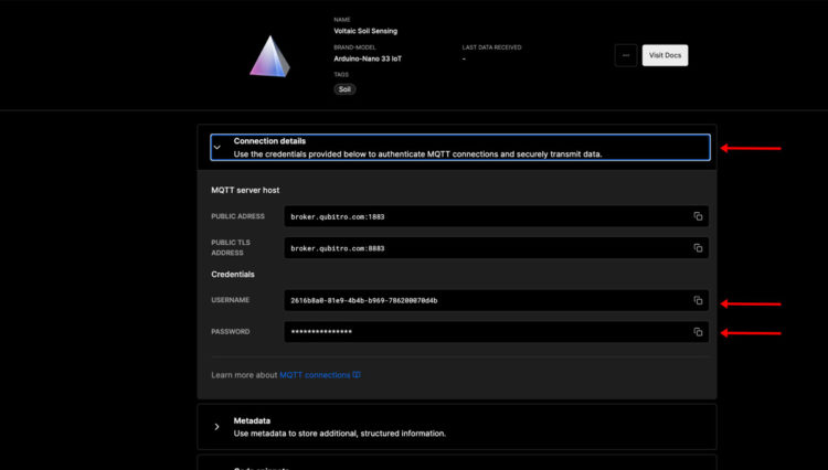
- You’ll need the USERNAME and PASSWORD for your Arduino Code.
- Create a New Sketch.
- Select your board and USB port.
- Create a new tab named “arduino_secrets.h”
- Complete the following:
[code lang=”arduino”]#define WiFi_ID "[YOUR Network]"
#define WiFi_PASSWORD "[YOUR password]"
#define DEVICE_ID "[Qubitro USERNAME]"
#define DEVICE_TOKEN "[Qubitro TOKEN]"
[/code] - Back in main Sketch, replace the current contents with the following:
[code lang=”arduino”]#include <QubitroMqttClient.h>
#include <WiFiNINA.h>
#include <Wire.h>
#include <DS3231.h>
#include <SPI.h>
#include <ModbusMaster.h>
#include "ArduinoLowPower.h"
#include "arduino_secrets.h"#define PERIOD 5000
// Global variables
DS3231 Clock;WiFiClient wifiClient;
QubitroMqttClient mqttClient(wifiClient);// WiFi Credentials
char ssid[] = WiFi_ID;
char pass[] = WiFi_PASSWORD;char deviceID[] = DEVICE_ID;
char deviceToken[] = DEVICE_TOKEN;
char host[] = "broker.qubitro.com";
int port = 1883;/* Modbus stuff */
#define MODBUS_DIR_PIN 10 // connect DR, RE pin of MAX485 to gpio 10
#define MODBUS_RX_PIN RX // Rx pin
#define MODBUS_TX_PIN TX // Tx pin
#define MODBUS_SERIAL_BAUD 4800 // Baud rate for max485 communicationunsigned long next = 0;
int publishCounter = 0;
int counter = 0;
int wifiCounter = 0;ModbusMaster node;
float moisture, pH, conductivity, temperature, voltage, battery;
// Pin 10 made high for Modbus transmision mode
void modbusPreTransmission() {
delay(500);
digitalWrite(MODBUS_DIR_PIN, HIGH);
}
// Pin 10 made low for Modbus receive mode
void modbusPostTransmission() {
digitalWrite(MODBUS_DIR_PIN, LOW);
delay(500);
}void setup() {
// Warm-up
delay(5000);
analogReadResolution(12);
// Start the I2C interface
Wire.begin();int wifiCounter = 0;
// Initialize serial port
Serial.begin(9600);// connect to Wifi network:
Serial.print("Connecting to WiFi…");
WiFi.begin(ssid, pass);
while (WiFi.status() != WL_CONNECTED) {
if (wifiCounter < 5) {
Serial.print(".");
delay(1000);
wifiCounter++;
status = WiFi.begin(ssid, pass);
} else {
LowPower.sleep(2000);
NVIC_SystemReset();
setup();
}
}Serial.println("\tConnected to the WiFi !");
// You need to provide device id and device token mqttClient.setId(deviceID);
mqttClient.setDeviceIdToken(deviceID, deviceToken);
Serial.println("Connecting to Qubitro…");
if (!mqttClient.connect(host, port)) {
Serial.println("Connection failed! Error code = ");
Serial.println(mqttClient.connectError());
Serial.println("Visit docs.qubitro.com or create a new issue on github.com/qubitro");
while (1) ;
}Serial.println("Connected to the Qubitro !");
mqttClient.onMessage(receivedMessage);
mqttClient.subscribe(deviceID);
// Initialize the RTC clock // Disable alarm Clock.turnOffAlarm(2);
// Disable oscialltor Clock.enableOscillator(false, false, 0);
// Disable 32kHz output Clock.enable32kHz(false);
// Set in 24-hour mode Clock.setClockMode(false);
// Serial communication Serial.begin(9600);
pinMode(MODBUS_DIR_PIN, OUTPUT);
digitalWrite(MODBUS_DIR_PIN, LOW);
counter = 0;
publishCounter = 0;//Serial1.begin(baud-rate, protocol, RX pin, TX pin);
Serial1.begin(MODBUS_SERIAL_BAUD);//modbus slave ID 1 node.begin(1, Serial1);
// callbacks allow us to configure the RS485 transceiver correctlynode.preTransmission(modbusPreTransmission);
node.postTransmission(modbusPostTransmission);// Prepare the next execution (defined by the day, hour, minute, second) + interval
// Interval:
// 0b1111 // each second
// 0b1110 // Once per minute (when second matches)
// 0b1100 // Once per hour (when minute and second matches)
// 0b1000 // Once per day (when hour, minute and second matches)
// 0b0000 // Once per month when date, hour, minute and second matches. Once per week if day of the week and A1Dy=true
// Every time the seconds match 4 (every minute at the 4th second, the system wakes up)
Clock.setA1Time(1, 2, 3, 4, 0b1110, false, false, false);
Clock.turnOnAlarm(1);// Empty the I2C buffer while (Wire.available()) { Wire.read();
}
Serial.println("here");
}void loop() {
mqttClient.poll();
if (millis() > next) {
next = millis() + PERIOD;// Change if possible to have a message over 256 characters
readModVals();
publishSensorVal();
publishCounter++;
}
}void receivedMessage(int messageSize) {
Serial.print("New message received:");
Serial.print(mqttClient.messageTopic());
Serial.print("', length ");
Serial.print(messageSize);
Serial.println(" bytes:");
// We want to read each character into a useable String
String content = "";
char character;
while (mqttClient.available()) {
character = Serial.print((char)mqttClient.read());
content.concat(character);
}
Serial.println(content);
Serial.println();
Serial.println();
timeToTurnOff();
}void timeToTurnOff() {
Serial.println("sleep");
Clock.checkIfAlarm(1);// We never arrive here because the alarm is cleared
// on the RTC which cause the shutdown of the circuit
while (1)
;
}//Modbus function 0x03 Read Holding Registers
result = node.readHoldingRegisters(0, 5);if (result == node.ku8MBSuccess) {
Serial.println("Success, Received data: ");Serial.print("Moisture: ");
// we just convert the uint16_t type data array to float type using type casting
moisture = float(node.getResponseBuffer(0)) * 0.1f;
temperature = float(node.getResponseBuffer(1)) * 0.1f;
conductivity = float(node.getResponseBuffer(2));
pH = float(node.getResponseBuffer(3)) * 0.1f;
float salinity = float(node.getResponseBuffer(4)) * 0.1f;Serial.print("Moisture: ");
Serial.print(moisture);
Serial.println("%");Serial.print("Temperature: ");
temperature = (temperature * 9) / 5 + 32;
Serial.print(temperature);
Serial.println("°F");Serial.print("Conductivity: ");
Serial.print(conductivity);
Serial.println("us/cm");Serial.print("pH value: ");
Serial.println(pH);<!–/*First, let’s divide the reading we’re getting from the ADC by 4095 to get a reading in what we could call ADC ‘units’. Now we have 4095ths of 3.3V incoming. Multiply by 3.3 to give us a voltage reading (dplus) We’re at the mid-point of the voltage divider, half the actual battery voltage, so to get the latter we need to multiply by 2.(voltage)*/ float dPlus = float(analogRead(A0)) / 4095 * 3.3; voltage = dPlus * 2 * 0.78; battery = voltage / 4.2 * 100; Serial.print("D+ "); Serial.println(voltage); Serial.print("Battery "); Serial.println(battery);–>
delay(1000);
}
}
}void publishSensorVal() {
// Change if possible to have a message over 256 characters
static char payload[256];snprintf(payload, sizeof(payload) – 1, "{\"m\":%.2f,\"t\":%.2f,\"c\":%.2f,\"pH\":%.2f}",
moisture, temperature, conductivity, pH);if (publishCounter >= 2) {
mqttClient.beginMessage(deviceID);
// Send value
mqttClient.print(payload);
mqttClient.endMessage();
delay(1000);
}
}
[/code] - Set up your Qubitro dashboard:
Characterizing Power Consumption
Now that we have taken steps to reduce the power consumption, we need to determine how much power our current system draws.
We need to measure the power consumption when sensing, transmitting, and sleeping. Once we have those values, we can use this calculator to determine what size panel we’ll need.
Power consumption of Microcontroller
Power consumption of Battery
Power consumption of RTC
Sensing/Awake Transmitting Sleeping Microcontroller 60mA 140mA 9mA RTC 0.1 mA 0.1 mA 0.1 mA 60.1 140.1 9.1 Time in seconds 20 1 60 Battery 0.6wh per day 0.6wh per day 0.6wh per day The device is consuming a whopping 3.39 Watt hours per day. If we change the sleep to every hour, we can bring down the consumption to 1.73 Watt hours per day which is more efficient and sustainable in terms of battery life.
Return to the code and update the length of sleep.
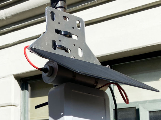
Connecting to Solar
If we use the 5 Watt, 6 Volt panel and V35 battery, our system should theoretically last about 20 days without sun.
Here’s how we connect the 5 Watt 5 Volt 35Wh Solar System
Wrapping up
This blog post has provided a comprehensive walkthrough for setting up and configuring, deploying and publishing data for a simple IoT device with the Nano 33. Let us know what you come up with in your next IoT project.
Enclosures can get very hot in sunny locations and very cold in many locations. This tutorial does not address all the safety issues associated with charging a lithium ion battery outdoors and you should understand these prior to deploying a battery powered system. Batteries charged outside of specifications can overheat and catch fire. Here are some key considerations for safely housing lithium-ion batteries in enclosures:
- Follow battery cell instructions for safe charging and storage
- Always use cables and adapters that are made specifically for the device
- Store and charge batteries away from anything flammable
- Ensure your charge controller includes over and under temperature protection and that these settings match the specifications on your battery cells
- Ensure your charge controller has over charge, over discharge and short circuit protection
If a battery changes shape or is leaking, you should discontinue use immediately.
Leave a Reply